background image

14

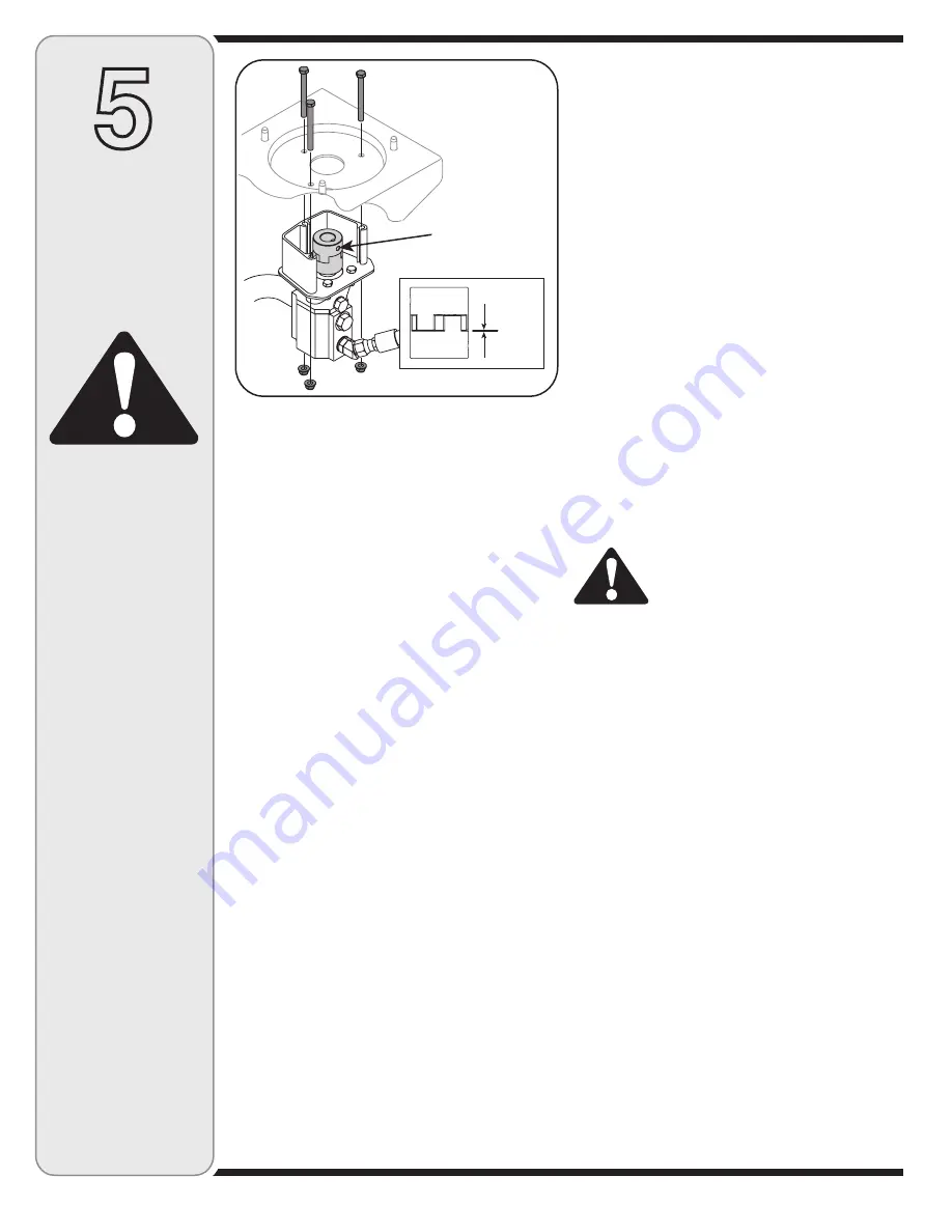
6.  Install pump coupling half and key on pump shaft. 

Rotate coupling half until set screw faces opening in 
shield. Do not tighten set screw.

7.  Install nylon “spider” onto engine coupling half.
8.  Align pump coupling half with nylon “spider” by rotat-

ing engine using starter handle. Slide coupling half 
into place while guiding three mounting bolts through 
holes in pump support bracket.

9.  Secure with nuts removed earlier.
10. Set.010” to.060” clearance/gap between the nylon 

“spider” and the engine coupling half by sliding a 
feeler gauge or matchbook cover between the nylon 
“spider” and the engine coupling half and moving 
pump coupling half as needed. Secure pump coupling 
half with set screw. See Figure 5-3.

NOTE

: Make certain proper clearance/gap is obtained 

before tightening set screw.

Tires

See sidewall of tire for recommended pressure. Under 
any circumstances do not exceed manufacturer’s recom-
mended psi. Maintain equal pressure on all tires.

WARNING: Excessive pressure when 
seating beads may cause tire/rim as-
sembly to burst with force sufficient to 
cause serious injury. Refer to sidewall 
of tire for recommended pressure.

WARNING

Figure 5-3

5

Maintaining 

Your Log 

Splitter

IMPORTANT

: Never hit the engine shaft in any manner, 

as a blow will cause permanent damage to the engine.

1.  Remove three nuts that secure the pump to the 

coupling shield. Two nuts are at the bottom corners 
and one is in the top center. See Figure 5-3.

2.  Remove the pump.
3.  Rotate the engine by slowly pulling starter handle 

until engine coupling half set screw is visible. Loosen 
set screw using allen wrench and slide coupling half 
off engine shaft.

4.  Loosen set screw on pump coupling half and remove 

coupling half.

5.  Slide new engine coupling half onto the engine 

shaft until the end of the shaft is flush with the inner 
portion of the coupling half. (There must be space 
between the end of the engine support bracket and 
coupling half). Tighten set screw.

Excessive pressure 

when seating beads 

may cause tire/rim 

assembly to burst 

with force sufficient to 

cause serious injury. 

Refer to sidewall of 

tire for recommended 

pressure.

.0600

.0100

Side View-Coupler

Set Screw

Summary of Contents for 24BF572B729

Page 1: ...orking order by the operator In the State of California the above is required by law Section 4442 of the California Public Resources Code Other states may have similar laws Federal laws apply on feder...

Page 2: ...s regarding the controls operation or maintenance of this unit you can seek help from the experts Choose from the options below 1 Visit mtdproducts com Click on Yardmachines and then the Customer Supp...

Page 3: ...ND PLATE 3TABILIZE THE LOG WHEN NEEDED ON ITS SIDES NEVER ON THE END BETWEEN THE LOG AND SPLITTING WEDGE NLY ONE ADULT SHOULD STABILIZE THE LOG AND OPERATE THE CONTROL OVE THE CONTROL HANDLE IN THE SP...

Page 4: ...des Take appropriate firefighting equipment with you 14 This machine should be used for splitting wood only do not use it for any other purpose 15 Follow the instructions in the manual s provided with...

Page 5: ...turn until it leans against the beam and is stable b When splitting extra large or uneven logs the log must be stabilized with wooden shims or split wood between the log and end plate or ground 12 Al...

Page 6: ...ue with the holes in the tank bracket and secure with hardware just removed See Figure 3 2 NOTE High pressure hose must be above the tongue assembly Connecting Cylinder to Beam The log splitter is shi...

Page 7: ...ipstick See Figure 3 7 Do not overfill 5 Replace vented dipstick securely tightening it until the top of the threads are flush with top of the pipe 6 Disconnect the spark plug and prime the pump by pu...

Page 8: ...cated on the beam support latch bracket See Figure 4 1 Engine Controls See the accompanying engine manual for the location and function of the controls on the engine IMPORTANT Your log splitter may be...

Page 9: ...or UP to return the wedge toward the cylinder The control handle stays in the return Reverse position and returns to neutral automatically when fully retracted NOTE Reverse position may also be opera...

Page 10: ...eck fluid level regularly 2 Use an approved hydraulic fluid Approved fluids include Dexron III Mercon III automatic transmis sion fluid a 10 Weight AW hydraulic oil or Pro Mix AW 32 Hydraulic Oil 3 Us...

Page 11: ...by turning over the engine with spark plug disconnected if not already done at factory 13 Split wood along the grain lengthwise only Never 1 Use when fluid is below 20 F or above 150 F 2 Use a solid...

Page 12: ...ng Always wear safety glasses during operation or while performing any adjustments or repairs Conditions that Will Void Warranty 1 Failure to maintain proper fluid level in reservoir 2 Changing the re...

Page 13: ...reservoir tank and hoses with kerosene whenever service is performed on the tank hydraulic pump or valve is recommended Contact an authorized service dealer Hydraulic Filter Change the hydraulic filt...

Page 14: ...when seating beads may cause tire rim as sembly to burst with force sufficient to cause serious injury Refer to sidewall of tire for recommended pressure WARNING Figure 5 3 5 Maintaining Your Log Spli...

Page 15: ...r Log Splitter 4 Start the engine and let it run until the fuel lines and carburetor are empty 5 Remove spark plug Holding a rag over the cylinder hole pour approximately 1 2 ounce approximately one t...

Page 16: ...with CHOKE applied if so equipped 2 Spark plug wire loose 3 Blocked fuel line or stale fuel 4 Water or dirt in fuel system 5 Dirty air cleaner 6 Carburetor not adjusted properly Cylinder rod will not...

Page 17: ...nder low load conditions 1 Correct alignment as necessary 2 See authorized service dealer 3 See authorized service dealer 4 Flush and clean hydraulic system 5 Flush and clean hydraulic system 1 Engine...

Page 18: ...0 71 33 55 44 45 15 18 19 64 17 61 41 41 69 58 57 56 34 65 41 44 67 62 72 59 66 48 23 51 29 30 27 59 82 50 72 18 61 11 12 3 4 6 80 5 79 7 8 9 44 65 70 41 41 39 43 38 35 14 52 53 54 73 48 26 28 37 23 3...

Page 19: ...4 Push Cap 38 732 0583 Compression Spring 39 781 04180 Log Tray Bracket 40 710 0650 TT Screw 5 16 18 x 875 41 712 04065 Flange Lock Nut 3 8 16 42 781 04179 Log Tray Ref No Part No Description 43 681 0...

Page 20: ...terior finish due to use or exposure d Service completed by someone other than an authorized service dealer e MTD does not extend any warranty for products sold or exported outside of the United State...

Reviews: