A-6
Realtek Audo
MS-7738
Append
x A
Backpanel audo jacks to 6-channel speakers dagram
Rear
Front
Center
& Subw
oofer
Backpanel audo jacks to 8-channel speakers dagram
Side Su
rround
■
Page 1: ...X79MA GD45 series MS 7738 v1 x Mainboard G52 77381X1...
Page 2: ...istered trademarks of AMD Corporation Intel is registered trademarks of Intel Corporation Windows is registered trademarks of Microsoft Corporation AMI is registered trademark of American Megatrends I...
Page 3: ...ment from overheating DO NOT COVER THE OPENINGS Make sure the voltage of the power source is at 110 220V before connecting the equipment to the power inlet Place the power cord such a way that people...
Page 4: ...ct the interference by one or more of the measures listed below Reorient or relocate the receiving antenna Increase the separation between the equipment and receiver Connect the equipment into an outl...
Page 5: ...rotection waste batteries should be collected separately for recycling or special disposal European Union Batteries battery packs and accumulators should not be disposed of as unsorted household waste...
Page 6: ...ronik Altger te nicht mehr als kommunale Abf lle entsorgt werden MSI hat europaweit verschiedene Sammel und Recyclingunternehmen beauftragt die in die Europ ische Union in Verkehr gebrachten Produkte...
Page 7: ...n voor de producten die de merknaam MSI dragen en verkocht zijn in de EU Deze goederen kunnen geretourneerd worden op lokale inzamelingspunten SRPSKI Da bi za titili prirodnu sredinu i kao preduze e k...
Page 8: ...ch sb rn ch MAGYAR Annak rdek ben hogy k rnyezet nket megv dj k illetve k rnyezetv d k nt fell pve az MSI eml kezteti nt hogy Az Eur pai Uni EU 2005 augusztus 13 n hat lyba l p az elektromos s elek tr...
Page 9: ...tting Started 1 1 Packing Contents 1 2 Optional Accessories 1 2 Assembly Precautions 1 3 Mainboard Specifications 1 4 Connectors Quick Guide 1 6 Back Panel Quick Guide 1 8 CPU Central Processing Unit...
Page 10: ...SECURITY 2 21 Appendix A Realtek Audio A 1 Installing the Realtek HD Audio Driver A 2 Software Configuration A 3 Hardware Default Setting A 5 Appendix B Intel RAID B 1 Introduction B 2 Using Intel RST...
Page 11: ...rd The Series mainboards are based on Intel X79 chipset for optimal system efficiency Designed to fit the advanced Intel LGA2011 processor the X79MA GD45 Series mainboards deliver a high per formance...
Page 12: ...rchase the optional accessories or request part numbers please visit the MSI website at http www msi com index php or consult the dealer Mainboard Drivers Utilities Disc User Guide Backplate SATA Cabl...
Page 13: ...handling the mainboard to prevent electrostatic damage If an ESD wrist strap is not available discharge yourself of static electricity by touching another metal object before han dling the mainboard S...
Page 14: ...for more information on compatible components please visit http www msi com service test report LAN Supports LAN 10 100 1000 Fast Ethernet by Realtek RTL8111E Audio Integrated HD audio codec by Realte...
Page 15: ...ort 6x audio ports On Board 2x USB 2 0 connectors 1x USB 3 0 connector 1x Serial port connector 1x TPM Module connector 1x Front Panel Audio connector 1x Chassis Intrusion connector 1x Voice Genie con...
Page 16: ...ectors Quick Guide Back Panel CPU CPUFAN1 JCOLD1 JPWR2 JPWR1 SATA1 2 JFP2 JFP1 JUSB3 JAUD1 JCI1 PCI_E1 JBAT1 SYSFAN2 SYSFAN1 JCOM1 SATA3 6 PCI_E2 PCI_E3 PCI_E4 DIMM2 DIMM1 DIMM3 DIMM4 JTPM1 JUSB2 JUSB...
Page 17: ...ATA 3Gb s Connectors SATA3 6 1 24 CPU Fan Connector CPUFAN1 1 25 System Fan Connectors SYSFAN1 2 1 25 Front Panel Connectors JFP1 JFP2 1 26 Front Panel Audio Connector JAUD1 1 26 USB 2 0 Expansion Con...
Page 18: ...ssion to external speakers through an coaxial cable Optical S PDIF Out This S PDIF Sony Philips Digital Interconnect Format connector is provided for digi tal audio transmission to external speakers t...
Page 19: ...a rate Orange On 1000 Mbits sec data rate Audio Ports These connectors are used for audio devices The color of the jack refers to the function of the connector Blue Line in Used for connecting externa...
Page 20: ...ord to ensure the safety of the CPU Overclocking This mainboard is designed to support overclocking Before attempting to overclock please make sure that all other system components can tolerate overcl...
Page 21: ...ways remember to install a CPU cooler A CPU cooler is necessary to prevent overheating and maintain system stability Follow the steps below to ensure correct CPU and CPU cooler installation Wrong inst...
Page 22: ...niform motion and latch to the socket 5 Line up the CPU to fit the CPU socket Be sure to hold the CPU by the base with the metal contacts facing downward The alignment keys on the CPU will line up wit...
Page 23: ...ating 10 Locate the CPU fan connector on the mainboard Thermal paste CPUFAN1 11 Place the heatsink on the mainboard with the fan s wires facing towards the fan connector and the screws matching the ho...
Page 24: ...re the mainboard with the screws provided with your computer case The locations of the screw holes on the mainboard are shown below For more information please refer to the manual that came with the c...
Page 25: ...3 V 1 3 3 V 1 4 1 2 V 2 3 3 V 1 5 G r o u n d 3 G r o u n d 1 6 P S O N 4 5 V 1 7 G r o u n d 5 G r o u n d 1 8 G r o u n d 6 5 V 1 9 G r o u n d 7 G r o u n d 2 2 5 V 1 0 1 2 V 2 0 R e s 8 P W R O K...
Page 26: ...memory modules can transmit and receive data with four data bus channels simultaneously to enhance system performance Important DDR3 memory modules are not interchangeable with DDR2 and the DDR3 stand...
Page 27: ...n off center notch on the bottom that will only allow it to fit one way into the DIMM slot Push the memory module deep into the DIMM slot The plastic clip at side of the DIMM slot will automatically c...
Page 28: ...erconnect Express Slot The PCIe slot supports the PCIe interface expansion card PCIe 2 0 x1 Slot PCIe 3 0 x16 Slot Important When adding or removing expansion cards always turn off the power supply an...
Page 29: ...on the mainboard Remove any protective expansion slot covers from the computer case Line up the video card on top of the expansion slot s with the display ports facing out of the computer case For a s...
Page 30: ...Link cable are required to connect the graphics cards Attach one side of the cable on each of the cards by way of the metal contacts please refer to the picture below Please note that although two gr...
Page 31: ...ng the operating system OS right click on the desktop and choose the Catalyst Control Center II 3 4 The CrossFireX setting must be enabled to allow CrossFireX mode to operate The follow screen appears...
Page 32: ...raphics cards in the PCI_E1 and the PCI_E3 slots With the two cards installed a SLI Video Link cable is required to connect the graphics cards Attach one side of the cable on each of the cards by way...
Page 33: ...Depending on your operating system the screen may look different 5 Important Please ensure that all graphics cards used in SLI mode are of the same brand and specifications For best compatibility wit...
Page 34: ...ly Such devices include disk drives HDD solid state drives SSD and optical drives CD DVD Blu Ray Please refer to the device s manual for further information Many computer cases also require that large...
Page 35: ...fan connector 1 G r o u n d 2 1 2 V 3 S e n s o r 4 C o n t r o l CPUFAN1 SYSFAN1 1 G r o u n d 2 1 2 V 3 S e n s o r N o U s e SYSFAN2 Important Please refer to your processor s official website or c...
Page 36: ...d L E D 5 P o w e r L E D 7 N o P i n 8 6 4 2 Buzzer Speaker JFP2 Important On the connectors coming from the case pins marked by small triangles are positive wires Please use the diagrams above and t...
Page 37: ...vert data channels to extra power channels to quickly charge your connected device Please note that when the SuperCharger application is turned on data transmission and synchronization over the JUSB1...
Page 38: ...C _ D P 1 3 G r o u n d 1 2 U S B 2 0 1 1 U S B 2 0 The MB layout in this figure is for reference only USB 3 0 Bracket optional Important Note that the VCC and GND pins must be connected correctly to...
Page 39: ...3 3 V P o w e r 2 3 V S t a n d b y p o w e r 1 L P C C l o c k 3 L P C R e s e t 5 L P C a d d r e s s d a t a p i n 0 7 L P C a d d r e s s d a t a p i n 1 9 L P C a d d r e s s d a t a p i n 2 1 1...
Page 40: ...n 6 V C C 3 4 C o n t r o l p i n 2 C o n t r o l p i n 1 5 V S B 3 C o n t r o l p i n 5 C o n t r o l p i n 7 C o n t r o l p i n 9 G r o u n d 1 1 R e s e r v e d p i n 1 3 G r o u n d MultiConnec...
Page 41: ...he PLL voltage is the voltage supplied to the process Phase Lock Loop DDR_C D Memory channel 2 and 3 voltage The DDR memory voltage is the voltage supplied to the DDR memory modules on the mainboard L...
Page 42: ...Data 1 1 Important You can clear the CMOS RAM by shorting this jumper while the system is off Afterwards open the jumper Do not clear the CMOS RAM while the system is on because it will damage the mai...
Page 43: ...ore reliable the power flow to the processor DIMM_WARNING LEDs These LEDs will light when the installed memories in DIMM2 and DIMM4 do not meet the mainboard design DrMOS_ALARM LED This LED will light...
Page 44: ......
Page 45: ...onitor CPU temperature select the boot device priority and view system information such as the CPU name DRAM capacity the OS version and the BIOS version Users can import and export parameter data for...
Page 46: ...mportant The items under each BIOS category described in this chapter are under continuous update for better system performance Therefore the description may be slightly differ ent from the latest BIO...
Page 47: ...and update SECURITY The security menu is used to keep unauthorized people from mak ing any changes to the settings You can use these security features to protect your system Boot device priority bar Y...
Page 48: ...eneral Help F4 CPU Specifications F5 Enter Memory Z F6 Load optimized defaults F10 Save Change and Reset F12 Save a screenshot to a FAT FAT32 USB drive Sub Menu If you find a point symbol to the left...
Page 49: ...m 1 to 31 can be keyed by numeric function keys year The year can be adjusted by users System Time This allows you to set the system time that you want usually the current time The time format is hour...
Page 50: ...spend state Blinking The power LED blinks to indicate the sleep suspend state Integrated Peripherals Press Enter to enter the sub menu Onboard Lan Controller This item allows you to enable disable the...
Page 51: ...enable disable the serial port Serial COM Port0 Settings Select an address and corresponding interrupt for the serial port Hardware Monitor Press Enter to enter the sub menu CPU Smart Fan Target Cont...
Page 52: ...rom S3 by USB Device The item allows the activity of the USB device to wake up the system from S3 Sus pend to RAM sleep state Resume From S3 S4 S5 by PS 2 Mouse Keyboard These items determine whether...
Page 53: ...ndon all changes Restore Defaults Use this item to load the optimized default values set by the BIOS vendor Boot Override The installed storage devices will appear on this menu you can select one of t...
Page 54: ...ry speed Read only Internal PLL Overvoltage This item is used to adjust the PLL voltage CPU Base Clock MHz This item allows you to set the CPU Base clock in MHz You may overclock the CPU by adjusting...
Page 55: ...ing is controlled by the SPD Serial Presence Detect EE PROM on the DRAM module Setting to Auto enables DRAM timings and the following Advanced DRAM Configuration sub menu to be determined by BIOS base...
Page 56: ...harge command tFAW This item is used to set the tFAW four activate window delay timing tWCL This item is used to set the tWCL Write CAS Latency timing tCKE This item is used to set the Pulse Width for...
Page 57: ...ltage SA CPU I O Voltage CPU PLL Voltage DDR CH_A B Voltage DDR CH_C D Voltage DDR CH_A CA Vref Voltage DDR CH_B CA Vref Voltage DDR CH_C CA Vref Voltage DDR CH_D CA Vref Voltage DDR CH_A DQ Vref Volt...
Page 58: ...the sub menu Hyper Threading Technology The processor uses Hyper Threading technology to increase transaction rates and reduces end user response times The technology treats the two cores inside the p...
Page 59: ...is a power management state that detects when the system is idle and lowers power consumption accordingly Package C State limit This field allows you to select a C state mode Long duration power limi...
Page 60: ...rd power phase switch feature to reach the best power saving Motherboard LED Control This item allows you to enable Auto disable disabled the mainboard phase LED C1E Support To enable this item to red...
Page 61: ...click the BROWSER to access the Internet e mail and instant messaging Installing Winki To install Winki follow the steps below Power on your computer and enter Windows operating system Insert MSI Driv...
Page 62: ...For HDD with single partition only the requirements for HDD Backup are An additional partition from another HDD ex USB HDD for HDD Backup to back up restore image to from it Executing Winki stored in...
Page 63: ...able This item allows to select particular BIOS file from the USB Storage FAT 32 format only drive And the system will boot from selected BIOS file Save current UEFI rom to file Please setup a specifi...
Page 64: ...te button on the BIOS UTILITIES menu The Winki must be installed 1 Setup the connection by click the setting button if necessary Click the next button Live Update will automatically detect the version...
Page 65: ...a set password press Enter when you are prompted to enter a new pass word A message will confirm the password is being disabled Once the password is disabled you can enter the setup and OS without au...
Page 66: ......
Page 67: ...vides 10 channel DAC that simul taneously supports 7 1 sound playback and 2 channels of independent stereo sound output multiple streaming through the Front Out Left and Front Out Right chan nels Appe...
Page 68: ...ould look slightly different if you install the drivers in different operating systems Insert the application DVD into the DVD ROM drive The setup screen will automati cally appear Click Driver tab Cl...
Page 69: ...screen You may double click the icon and the GUI will pop up accordingly double click the icon It is also available to enable the audio driver by clicking the Realtek HD Audio Manager from the Control...
Page 70: ...just the bar Application Enhancement The array of options will provide you a complete guidance of anticipated sound effect for both output and input device Jack status panel This panel depicts all ren...
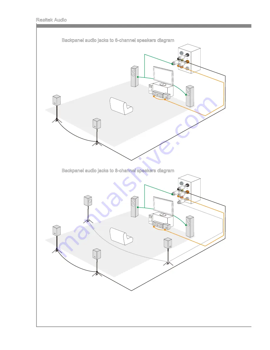
Page 71: ...S 7738 Appendix A Hardware Default Setting The following diagrams are audio back panel default setting Backpanel audio jacks to 2 channel speakers diagram Front Backpanel audio jacks to 4 channel spea...
Page 72: ...A 6 Realtek Audio Backpanel audio jacks to 6 channel speakers diagram Rear Front Center Subwoofer Backpanel audio jacks to 8 channel speakers diagram Rear Front Center Subwoofer Side Surround...
Page 73: ...This appendix will assist users in configuring and en abling RAID functionality and accelerating system on platforms Appendix B Intel RAID...
Page 74: ...cy by mirroring data between the hard drives and pro vides enhanced read performance RAID 5 Provides data striping at the byte level and also stripe error correction informa tion This results in excel...
Page 75: ...lume may be configured using the RAID Configuration utility stored within the Intel RAID Option ROM During the Power On Self Test POST the following message will appear for a few seconds Important The...
Page 76: ...r usage model in RAID Level 1 CREATE VOLUME MENU HELP Name RAID 1 Mirrors data redundancy Change TAB Next ESC Previous Menu ENTER Select RAID Level Disks Strip Size Capacity Volume0 RAID1 Mirror Selec...
Page 77: ...ecome available according to the selected RAID level Then select the capacity of the volume in the Capacity field The default value is the maximum volume capacity of the selected disks 2 3 4 CREATE VO...
Page 78: ...rip Size Capacity Volume0 RAID1 Mirror Select Disks N A XXX X GB Create Volume WARNING ALL DATA ON SELECTED DISKS WILL BE LOST Are you sure you want to create this volume Y N DISK VOLUME INFORMATION 3...
Page 79: ...elect a RAID volume for deletion Then press Delete key to delete the selected RAID volume The following screen appears DELETE VOLUME MENU HELP Deleting a volume will reset the disks to non RAID Select...
Page 80: ...structures and revert it to a non RAID disk RESET RAID DATA WARNING Resetting a disk causes all data on the disk to be lost This does not apply to Recovery volumes Select the disks that should be rese...
Page 81: ...driver into the A drive Note For Windows XP you can use the USB floppy drive only For Windows Vista Windows 7 you can use CD DVD USB drive 1 2 3 Important Please follow the instruction below to make...
Page 82: ...river Disc into the optical drive The setup screen will automatically appear Under the Driver tab click on Intel RAID Drivers The drivers will be automatically installed Confirming Windows Driver Inst...
Page 83: ...of the destination disk for rebuilding and then press ENTER 4 RAID Volumes ID Name Level Strip Size Status Bootable 0 Volume0 RAID 1 Mirror N A XXX XGB Degraded Yes Physical Disks Port Device Model Se...
Page 84: ...Intel RAID Exit Intel RAID Option ROM and then reboot to Windows system Run Intel Rapid Storage Technology enterprise application The control panel will display the current status of rebuilding proces...