MSI WindBOX Series User Manual Download Page 3

iii

Safety Instructions

1.

Always read the safety instructions carefully.

2.

Keep this user

s manual for future reference.

3.

Keep this equipment away from humidity.

4.

Lay this equipment on a reliable flat surface before setting it up.

5.

The openings on the enclosure are for air convection hence protects the
equipment from overheating. DO NOT COVER THE OPENINGS.

6.

Check the AC input: 100-240V~, 50-60Hz, 1.7A.

7.

Check the DC output: 20V 

 2.0A.

8.

Make sure that the power voltage is within its safety range and has been
adjusted properly to the value of 100~240V before connecting the equipment
to the power inlet.

9.

Place the power cord in a way that people are unlikely to step on it. Do not
place anything on the power cord.

10.

Always unplug the power cord before inserting any add-on card or module.

11.

All cautions and warnings on the equipment should be noted.

12.

Never pour any liquid into the opening that could damage or cause electrical
shock.

13.

If any of the following situations arises, get the equipment checked by ser-
vice personnel:

 The power cord or plug is damaged.
 Liquid has penetrated into the equipment.
 The equipment has been exposed to moisture.
 The equipment does not work well or you can not get it work according to

user

s manual.

 The equipment has dropped and damaged.
 The equipment has obvious sign of breakage.

14.

DO NOT LEAVE THIS EQUIPMENT IN AN ENVIRONMENT UNCONDITIONED,
STORAGE TEMPERATURE ABOVE 40

C (102

o

F), IT MAY DAMAGE THE

EQUIPMENT.

WARNING:

1.

For every changes in power cord

s usage, please use an approved power

cord with condition greater or equal to H05VV-F, 3G, 0.75mm

2

.

2.

Internal part is hazardous moving parts, please keep fingers and other body
parts away.

3.

For pluggable equipment, the socket-outlet shall be installed near the equip-
ment and shall be easily accessible.

4.

Do not disable the protective earth pin from the plug, the equipment must be
connected to an earthed mains socket-outlet.

CAUTION:

Danger of explosion if battery is incorrectly replaced. Replace only with the same or
equivalent type recommended by the manufacturer.

1.

The optical storage devices are classified as a Class 1 Laser products.
Use of controls or adjustments or performance of procedures other
than those specified.

2.

Do not touch the lens inside the drive.

廢電 池 請 回 收

For better environmental protection, waste batteries should be
collected separately for recycling or special disposal.

Summary of Contents for WindBOX Series

Page 1: ...i WindBOX Series G52 9A151X1 ...

Page 2: ...d trademark of Novell Inc Award is a registered trademark of Phoenix Technologies Ltd AMI is a registered trademark of American Megatrends Inc U S Patent Numbers 4 631 603 4 819 098 4 907 093 5 315 448 and 6 516 132 This product incorporates copyright protection technology that is protected by U S patents and other intellectual property rights Use of this copyright protection tech nology must be a...

Page 3: ... into the equipment The equipment has been exposed to moisture The equipment does not work well or you can not get it work according to user s manual The equipment has dropped and damaged The equipment has obvious sign of breakage 14 DONOTLEAVETHIS EQUIPMENTINANENVIRONMENTUNCONDITIONED STORAGE TEMPERATURE ABOVE 40o C 102o F IT MAY DAMAGE THE EQUIPMENT WARNING 1 For every changes in power cord s us...

Page 4: ... interference by one or more of the measures listed below Reorient or relocate the receiving antenna Increase the separation between the equipment and receiver Connect the equipment into an outlet on a circuit different from that to which the receiver is connected Consult the dealer or an experienced radio television technician for help Notice 1 The changes or modifications not expressly approved ...

Page 5: ...v WEEE Waste Electrical and Electronic Equipment Statement ...

Page 6: ...vi ...

Page 7: ...vii ...

Page 8: ...rt ii Safety Instruction iii FCC B Radio Frequency Interference Statement iv WEEE Waste Electrical and Electronic Equipment Statement v Chapter 1 Getting Started 1 1 System Specifications 1 2 System Outlooks 1 4 Packing Contents 1 6 Chapter 2 System Assembly 2 1 Necessary Tools 2 2 Assembly Porcedures 2 2 ...

Page 9: ...tarted Getting Started Chapter 1 Congratulations for purchasing the WindBOX This is your best choice for slim system It can easily be set anywhere The feature packed platform also gives you an exciting PC experience ...

Page 10: ...pset North Bridge Intel 945GSE chipset South Bridge Intel ICH7M chipset Display Intel GMA 950 chipset Resolution is up to QXGA 2048 x 1536 Memory Supports DDR2 400 533 SDRAM 200 Pin 1 8 V 1 DDR2 SO DIMM slot 1 GB Max Non ECC Audio Chip integrated by Realtek ALC888S HD audio Codec with auto jack sensing LAN Supports 10 100 Fast Ethernet by Realtek RTL8102E Compliant with PCI 2 3 Supports ACPI Power...

Page 11: ...1 3 in l card reader SD MMC MS 1 DC jack 1 SMA connector for WLAN antenna Power Supply 40 Watt Power Adapter with Active PFC Input 100 240V 50 60Hz 1 7A Output 20V 2 0A Form Factor 260 mm W X 180 mm D X 19 mm H 1 08 Kg Operation Environment Temperature 0o C 35o C Humidity 5 90 non condensing Storage Environment Temperature 20o C 80o C Humidity 5 90 non condensing ...

Page 12: ...a great view of the computer display Headphone Used for speakers or headphones Microphone Used for an external microphone Card Reader The built in card reader may support various types of memory card such as MMC Multi Media Card SD Secure Digital MS Memory Stick or cards USB Port The USB 2 0 port allows you to connect USB interface peripheral devices such as the mouse keyboard modem portable hard ...

Page 13: ...ith a key or some mechanical PIN device and attached through a rubberised metal cable The end of the cable has a small loop which allows the whole cable to be looped around a permanent object such as a heavy table or other similar equipment thus securing the system in place Power Button Press the power button to turn the system power ON and OFF Power Connector Connect the adapter and supply power ...

Page 14: ...of the item is damaged or missing The picture is for your reference only and your packing contents may slightly vary depending on the model you purchased Packing Contents WindBOX Power Adapter Power Cord User Manual Driver CD Back Mount Package WLAN Antenna ...

Page 15: ...you with the information about system assembly procedures While doing the installation be careful in holding the components and follow the installation procedures Use a grounded wrist strap before handling computer components Static electricity may damage the components ...

Page 16: ...etter Rubber gloves can prevent yourself from suffering the static charge Assembly Procedures 1 Find the screw holes on the back of the LCD 2 Use the corss type screwdriver to fix the back mount plate with the attached screws Important Choose the LCD less than 5 8 Kg for keeping the weight balance otherwise it may cause fall or related hazard ...

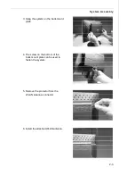
Page 17: ...ly 3 Hang the system on the back mount plate 5 Remove the protector from the WLAN antenna connector 4 The screw on the bottom of the back mount plate can be used to fasten the system 6 Install the attached WLAN antenna ...

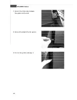
Page 18: ...2 4 WindBOX Series 7 Connect the VGA cable between the system and the LCD 9 Turn on the system and enjoy it 8 Connect the adaptor the the system ...

Reviews: