background image


30 

11. Dr

ü

cken Sie die vier Stifte nach unten um den K

ü

hler zu arretieren. Drehen 

Sie  dann  jeweils  den  Verschluss  der  Stifte  (Richtung  ist  auf  dem  K

ü

hler 

markiert). 

  
12.  Drehen  Sie  das  Mainboard  um  und  vergewissern  Sie  sich, 

dass das der K

ü

hler korrekt installiert ist.   


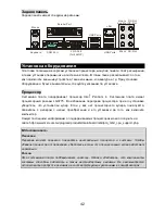
MSI weist darauf hin


1.Stellen Sie sicher, dass der CPU-K

ü

hler richtig installiert ist befor Sie das System anschalten. 

2.Pr

ü

fen Sie nach dem Einschalten die Anzeigen zur CPU-Temperatur in dem BIOS Bereich PC 

Health Status von H/W Monitor. 

3.Ber

ü

hren Sie keinesfalls die Pins des CPU-Sockels um Sch

ä

den zu vermeiden. 

4.Wenn  keine  CPU  installiert  ist,  sch

ü

tzen  Sie  immer  den  CPU-Sockel  durch  die 

Plastikabdeckung. 

5.Beachten  Sie  bitte,  dass  die CPU  nur  f

ü

r  maximal  20  Ein-/und  Ausbauten entworfen wurde. 

Aus  diesem  Grund  schlagen  wir  vor,  dass  Sie  sie  nicht  allzu  h

ä

ufig  entnehmen  und  wieder 

einsetzen. 

 
Speicher 

Das Mainboard verf

ü

gt 

ü

ber zwei Sockel f

ü

r ungepufferte 240-Pin DDRII 533/ DDRII 667 

SDRAM DIMMs und unterst

ü

tzt den Speicherausbau auf bis zu 2 GB. Um einen 

ordnungsgem

äß

en Betrieb zu erm

ö

glichen, muss mindestens ein DIMM- Speichermodul 

eingesetzt sein. (Um den letzten Stand bez

ü

glich der unterst

ü

tzten Speichermodule zu erhalten, 

besuchen Sie http://www.msi.com.tw/program/products/mainboard/mbd/pro_mbd_trp_list.php)


Setzen  Sie  mindestens  ein  Speichermodul  in  einem  Stecksockel  ein.  Die  Module  k

ö

nnen  in 

beliebiger  Reihenfolge  eingesetzt  werden.  Gem

äß

  Ihren  Anforderungen  k

ö

nnen  Sie  entweder 

einseitige oder doppelseitige Module verwenden. 


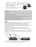
  Vorgehensweise beim Einbau von DDRII Modulen 


1.  Die Speichermodul haben nur eine Kerbe in der Mitte des Moduls. Sie passen nur in einer 

Richtung in den Sockel.   

2.  Setzen Sie den DIMM- Speicherbaustein senkrecht in den DIMM- Sockel, dann dr

ü

cken Sie 

ihn hinein, bis die goldenen Kontakte tief im Sockel sitzen. 

3.  Die Plastikklammern an den Seiten des DIMM- Sockels schlie

ß

en sich automatisch. 

Notch

Volt

Summary of Contents for MS-7277

Page 1: ...e by one or more of the measures listed below 4 Reorient or relocate the receiving antenna 4 Increase the separation between the equipment and receiver 4 Connect the equipment into an outlet on a circ...

Page 2: ...marks of International Business Machines Corporation Microsoft is a registered trademark of Microsoft Corporation Windows 98 2000 NT XP are registered trademarks of Microsoft Corporation NVIDIA the NV...

Page 3: ...erting any add on card or module 9 All cautions and warnings on the equipment should be noted 10 Never pour any liquid into the opening that could damage or cause electrical shock 11 If any of the fol...

Page 4: ...s la poubelle Les fabricants de ces quipements seront oblig s de r cup rer certains produits en fin de vie MSI prendra en compte cette exigence relative au retour des produits en fin de vie au sein de...

Page 5: ...al nmas iste i ile i birli i i erisinde olacakt r r nlerinizi yerel toplama noktalar na b rakabilirsiniz ESKY Z le n m na ochran ivotn ho prost ed spole nost MSI upozor uje Podle sm rnice Evropsk uni...

Page 6: ...vi Table of Content English 1 Fran ais 13 Deutsch 25 39 53 65 77...

Page 7: ...Threading Technology in the LGA775 package the 946GZM 946PLM series delivers a high performance and professional desktop platform solution Layout BATT IDE1 ATX1 JCI1 JCOM1 optional JPWR1 DIMM1 DIMM2 P...

Page 8: ...Max 2 DDRII DIMM slots 240 pin non ECC For the updated supporting memory modules please visit http www msi com tw program products mainboard mbd pro_mbd_trp_list php LAN optional Supports 10 100 LAN b...

Page 9: ...supporting SPP EPP ECP mode 1 Serial port 1 VGA port for 946GZ only 4 USB 2 0 ports 1 LAN jack 6 audio jacks On Board Pinheaders 1 COM pinheader 2 USB pinheaders 1 SPDIF_out pinheader Slots 1 PCI Expr...

Page 10: ...oler contact your dealer to purchase and install them before turning on the computer For the latest information about CPU please visit http www msi com tw program products mainboard mbd pro_mbd_cpu_su...

Page 11: ...over it to protect the socket pin 2 Remove the cap from lever hinge side 3 The pins of socket reveal 4 Open the load lever 5 Lift the load lever up and open the load plate 6 After confirming the CPU d...

Page 12: ...nly one notch on the center of module The module will only fit in the right orientation 2 Insert the memory module vertically into the DIMM slot Then push it in until the golden finger on the memory m...

Page 13: ...high speed Serial ATA interface ports The ports support 2nd generation Serial ATA data rates of 300 MB s and are fully compliant with Serial ATA 2 0 specifications Each Serial ATA connector can connec...

Page 14: ...at the pins of VCC GND must be connected correctly or it may cause some damage Serial Port Connector JCOM1 optional The mainboard provides one serial port header for you to connect secondary serial de...

Page 15: ...s a high performance graphics infrastructure for Desktop Platforms doubling the capability of existing AGP 8x designs with transfer rates of 4 0 GB s over a PCI Express x16 lane for graphics controlle...

Page 16: ...eatures Use this menu to setup the items of Award special enhanced features Advanced Chipset Features Use this menu to change the values in the chipset registers and optimize your system performance I...

Page 17: ...Configure DRAM Timing by SPD Selects whether DRAM timing is controlled by the SPD Serial Presence Detect EEPROM on the DRAM module Setting to Enabled enables DRAM timings to be determined by BIOS bas...

Page 18: ...MHz and overclock the processor by adjusting the FSB clock to a higher frequency Adjusted CPU Clock It shows the CPU clock Read only DRAM Frequency User can place an artificial memory clock limit on t...

Page 19: ...la technologie de Hyper Threading gr ce au LGA775 Les s ries 946GZM 946PLM sont tr s performantes et offrent une solution adapt e tant aux professionnels qu aux particuliers Sch ma BATT IDE1 ATX1 JCI...

Page 20: ...DDRII 533 667 SDRAMs jusqu 2GB Supporte deux DIMMs DDRII de 240 pin non ECC Pour plus d informations http www msi com tw program products mainboard mbd pro_mbd_trp_list php LAN option Supporte 10Mb s...

Page 21: ...e qui supporte les modes SPP EPP ECP 1 port s rie 1 port VGA pour 946GZ seulement 4 ports USB 2 0 1 LAN jack 6 jacks audio Connecteurs int gr s 1 connecteur COM 2 connecteurs USB 1 connecteur Sortie S...

Page 22: ...i qu un ventilateur afin d viter toute surchauffe Si vous ne savez pas le mod le qu il vous faut il est recommand de prendre contact avec votre revendeur Veuillez vous rendre sur le site pour plus d i...

Page 23: ...leure dissipation de la chaleur 1 Le socket CPU poss de un plastique de protection Ne le retirer qu au moment d installer le CPU 2 Enlevez le chapeau de la charni re du levier 3 Les broches de la doui...

Page 24: ...vous en avez besoin Installez Ies Modules DDRII 1 La DIMM ne poss de qu une encoche en son centre Ainsi il n est possible de monter le module que dans un seul sens 2 Ins rez verticalement le module de...

Page 25: ...rts supportent la deuxi me g n ration de S rie ATA avec un taux de donn e de 300MB et ils sont compatibles avec les caract ristiques de S rie ATA 2 0 Chaque connecteur ATA peut se relier 1 un disque d...

Page 26: ...connect es afin d viter tout dommage Connecteur Port s rie JCOM1 option La carte m re dispose d un connecteur port s rie pour vous permettre de connecter un second mat riel s rie Connecteur Sortie SP...

Page 27: ...mances graphiques pour plateformes Desktop et qui double la capacit existante d AGP 8x avec un taux de transfert de 4 0 GB s hors de la voie PCI Express x16 pour les contr leurs graphiques MSI Vous Ra...

Page 28: ...ion permet de param trer des l ments avanc s du BIOS Advanced Chipset Features Cette option vous permet de param trer les l ments relatifs au registre du chipset permettant ainsi d optimiser les perfo...

Page 29: ...setup Advanced Chipset Features Configurez DRAM Timing par SPD Choisissez si le minutage DRAM est contr l par le SPD Serial Presence Detect EEPROM sur Ie Modules DRAM Allez sur Enabled pour permettre...

Page 30: ...s CPU Lecture unique DRAM Frequency Cette fonction vous permet de pr ciser une fr quence de m moire artificielle sur ce syst me L objectif tant d viter que la m moire aille plus vite que cette fr quen...

Page 31: ...t tzt Hyper Threading Technologie im LGA 775 Package stellt das Mainboard 946GZM 946PLM Series die ideale Losung zum Aufbau eines professionellen Hochleistungsdesktopsystems dar Layout BATT IDE1 ATX1...

Page 32: ...ECC Um den letzten Stand bez glich der unterst tzten Speichermodule zu erhalten besuchen Sie bitte http www msi com tw program products mainboard mbd pro_mbd_trp_list php LAN Unterst tzt 10 100 LAN m...

Page 33: ...telle die Betriebmodi SPP EPP ECP unterst tzt 1 Serielle Port 1 VGA Port nur f r 946GZ 4 USB 2 0 Ports 1 LAN Buchse 6 Audio Buchse On Board Stiftleisten 1 COM Stiftleiste 2 USB Stiftleisten 1 SPDIF_Au...

Page 34: ...in Verbindung um einen solchen zu erwerben und danach zu installieren bevor Sie Ihren Computer anschalten Um die neuesten Informationen zu unterst tzten Prozessoren zu erhalten besuchen Sie bitte http...

Page 35: ...Schutz eine Plastikabdeckung Lassen Sie vor der Installation diese Schutzkappe auf dem Sockel um Sch den zu vermeiden 2 Entfernen Sie zuerst die Schutzkappe wie abgebildet in Pfeilrichtung 3 Sie sehe...

Page 36: ...r einsetzen Speicher Das Mainboard verf gt ber zwei Sockel f r ungepufferte 240 Pin DDRII 533 DDRII 667 SDRAM DIMMs und unterst tzt den Speicherausbau auf bis zu 2 GB Um einen ordnungsgem en Betrieb z...

Page 37: ...allation die Pins 11 12 23 und 24 vertauschungssicher gestaltet ATX 12V Stromanschluss JPWR1 Dieser 12V Stromanschluss wird verwendet um die CPU mit Strom zu versorgen Anschluss des Diskettenlaufwerks...

Page 38: ...Netzteill fter unterst tzen aktive Systeml fter mit 12V CPUFAN unterst tzt sowohl drei als auch vierpolige Stecker Wenn Sie den Stecker mit dem Anschluss verbinden sollten Sie immer darauf achten dass...

Page 39: ...Anschluss verbinden SPDIF Ausgang J2 optional Die SPDIF Sony Philips Digital Interconnect Format Schnittstelle wird f r die bertragung digitaler Audiodaten verwendet Steckbr cke zur CMOS L schung J1...

Page 40: ...estehender AGP8x Designs mit bertragungsraten von 4 0 Gbit Sek ber eine PCI Express 16 fach Leitung f r Grafikkarten verdoppelt w hrend PCI Express 1 fach bertragungsraten von 250 MBit Sek unterst tzt...

Page 41: ...ndard BIOS Features In diesem Men k nnen Sie die Basiskonfiguration Ihres Systems anpassen so z B Uhrzeit Datum usw Advanced BIOS Features Verwenden Sie diesen Men punkt um AMI eigne weitergehende Ein...

Page 42: ...it Setup Abspeichern der BIOS nderungen im CMOS und verlassen des BIOS Exit Without Saving Abspeichern der BIOS nderungen im CMOS und verlassen des BIOS Advanced Chipset Features Configure DRAM Timing...

Page 43: ...gehende Taktsteigerung erzeugen kann die gerade ausreichen mag um Ihren bertakteten Prozessor zum einfrieren zu bringen Adjust CPU FSB Frequency Gestattet die Wahl der CPU Front Side Bus Taktfrequnez...

Page 44: ...n f hren deswegen wird von einer langfristigen nderung der DDR Spannung ABGERATEN Chipset Voltage V Die Anpassung der Chipsatz Spannung kann die Chipsatz Geschwindigkeit erh hen Jegliche nderung and d...

Page 45: ...75 BATT IDE1 ATX1 JCI1 JCOM1 optional JPWR1 DIMM1 DIMM2 PWRFAN1 SYSFAN1 CPUFAN1 PCI2 ALC883 RTL8100C PCI1 PCI_E2 JAUD1 CD_IN1 J2 FDD1 JUSB2 JUSB1 J1 JFP1 SATA4 SATA1 SATA3 SATA2 JFP2 Intel ICH7 ICH7R...

Page 46: ...pu_support php FSB 800 Intel 946GZ 946PL Intel ICH7 ICH7R DDRII 533 667 SDRAM 2 Max 2 DDRII DIMM 240 non ECC http www msi com tw program products mainboard mbd pro_mbd_trp_list php http www microstar...

Page 47: ...CH7R 300 M SATA RAID ICH7R Floppy 1 1 FDD 360K 720K 1 2M 1 44M 2 88 1 PS 2 1 PS 2 1 SPP EPP ECP 1 1 VGA 946GZ 4 USB 2 0 1 LAN 6 1 COM 2 USB 1 SPDIF 1 PCI Express x 16 1 PCI Express x 1 2 PCI 3 3V 5V P...

Page 48: ...m 4 LGA775 http www msi com tw program products mainboard mbd pro_mbd_cpu_support php MSI Mouse Parallel Port COM Port VGA Port for 946GZ USB Ports USB Ports LAN Line In RS Out SS Out Mic In Line Out...

Page 49: ...43 LGA775 LGA775 LGA 775 LGA 775 1 2 3 4 5 6 7 8 9...

Page 50: ...onitor 3 4 5 20 240 DDRII 533 DDRII 667 SDRAM DIMM 2 DIMM http www msi com tw program products mainboard mbd pro_mbd_trp_list php http www microstar ru program products mainboard mbd pro_mbd_ trp_list...

Page 51: ...360K 720K 1 2M 1 44M 2 88M IDE IDE1 Ultra DMA 66 100 PIO mode 0 4 Bus Master Ultra DMA 66 100 CD ROM 120 IDE1 Master Slave Slave MSI IDE Slave GND GND GND PS ON GND 3 3V 12V 3 3V 3 3V 3 3V 5V 5V 5V 5...

Page 52: ...A CD In CD_IN1 CD ROM JCI1 CPUFAN1 SYSFAN1 PWRFAN1 CPUFAN1 SYSFAN1 PWRFAN1 12 12 GND MSI JFP1 JFP2 JFP1 Intel Front Panel I O Connectivity Design Guide GND 12V NC GND L R CINTRU GND GND 12V Sensor Con...

Page 53: ...D JCOM1 SPDIF Out J2 SPDIF Sony Philips Digital Interconnect Format CMOS J1 CMOS CMOS CMOS J1 CMOS 10 Line_JD GND 2 VCC5 MIC2_JD NC MIC_L 1 Line out_R 9 Line out_L MIC_R Front to Sense 10 N C VCC 2 US...

Page 54: ...Express x1 Gigabit Ethernet 1394 PCI Express MSI PCI Peripheral Component Interconnect PCI BIOS PC IRQ Interrupt ReQuest line Order1 Order2 Order3 Order4 PCI Slot 1 INT A INT B INT C INT D PCI Slot 2...

Page 55: ...up F11 Boot Menu TAB Logo RESET Ctrl Alt Delete Standard BIOS Features Advanced BIOS Features Advanced Chipset Features Integrated Peripherals Power Management Setup PNP PCI Resource Management PnP PC...

Page 56: ...BIOS BIOS Setting Password Save Exit Setup CMOS Exit Without Saving Advanced Chipset Features Configure DRAM Timing by SPD DRAM SPD SPD Serial Presence Detect EEPROM DRAM DRAM Enabled DRAM SPD Intern...

Page 57: ...lectromagnetic Interference Spread Spectrum Disabled Enable Spread Spectrum Adjust CPU FSB Frequency FSB AGP PCI FSB Adjusted CPU Clock DRAM Frequency DRAM Adjusted Memory Frequency Auto Disable PCI C...

Page 58: ...52 Memory Voltage DDR DDR Chipset Voltage V...

Page 59: ...M BATT IDE1 ATX1 JCI1 JCOM1 optional JPWR1 DIMM1 DIMM2 PWRFAN1 SYSFAN1 CPUFAN1 PCI2 ALC883 RTL8100C PCI1 PCI_E2 JAUD1 CD_IN1 J2 FDD1 JUSB2 JUSB1 J1 JFP1 SATA4 SATA1 SATA3 SATA2 JFP2 Intel ICH7 ICH7R I...

Page 60: ...MHz Intel 946GZ 946PL Intel ICH7 ICH7R DDRII 533 667 SDRAM 2 GB 2 DDRII DIMM 240 pin non ECC http www msi com tw program products mainboard mbd pro_mbd_trp_list php LAN Realtek RTL8100C 10 100 LAN Rea...

Page 61: ...60K 720K 1 2M 1 44M 2 88Mbytes FDD 1 PS 2 1 PS 2 1 SPP EPP ECP 1 1 VGA 946GZ 4 USB 2 0 1 LAN 6 1 COM 2 USB 1 SPDIF 1 PCI Express x 16 1 PCI Express x 1 2 PCI 3 3V 5V PCI Micro ATX Form Factor 244mm x...

Page 62: ...A775 CPU CPU CPU CPU http www msi com tw program products mainboard mbd pro_mbd_cpu_support php CPU CPU Mouse Parallel Port COM Port VGA Port for 946GZ USB Ports USB Ports LAN Line In RS Out SS Out Mi...

Page 63: ...57 LGA775 CPU CPU CPU CPU CPU CPU CPU LGA 775 CPU LGA 775 CPU LGA 775 CPU CPU 1 CPU CPU CPU 2 3 4 5 CPU 6 CPU CPU CPU CPU 7 CPU CPU 8 9 10 11 12 1 CPU 2 BIOS CPU 3 CPU 4 CPU CPU 5 CPU 20 CPU...

Page 64: ...IMM 3 DIMM ATX 350W ATX 24 Pin ATX1 ATX 24 pin ATX 24 pin 20 pin ATX 20 pin ATX 1 13 11 12 23 24 ATX 12V JPWR1 12V CPU FDD1 360K 720K 1 2M 1 44M 2 88M IDE IDE1 Ultra DMA 66 100 PIO 0 4 Ultra DMA 66 10...

Page 65: ...1 PWRFAN1 4 pin CPUFAN1 3 pin SYSFAN1 PWRFAN1 12V 12V CPU JFP1 JFP2 JFP1 Intel I O JAUD1 Intel I O GND 12V NC GND L R CINTRU GND GND 12V Sensor Control GND 12V NC JFP1 Power LED HDD LED Reset Switch P...

Page 66: ...MOS PCI Express PCI Express Intel HT Pentium 4 PCI Express I O 2 5 Giga PCI Express x1 Gigabit Ethernet TV 1394 I O PCI Express PCI Express PCI Express x16 APG8x 2 4 0 GB s PCI Express X 1 slot PCI Ex...

Page 67: ...61 PCI PCI BIOS PCI IRQ Order1 Order2 Order3 Order4 PCI Slot 1 INT A INT B INT C INT D PCI Slot 2 INT B INT C INT D INT A...

Page 68: ...BIOS Advanced BIOS Features BIOS Award Advanced Chipset Features Integrated Peripherals Power Management Features PNP PCI Resource Management PNP PCI PnP PCI H W Monitor CPU Cell Menu Load Optimal Def...

Page 69: ...63 Configure DRAM Timing by SPD SPD DRAM DRAM SPD EEPROM Enabled BIOS SPD Internal Graphics Mode Selec BIOS...

Page 70: ...abled Enabled Adjust CPU FSB Frequency CPU FSB CPU MHZ FSB Adjusted CPU Clock CPU CPU DRAM Frequency DRAM Adjusted Memory Frequency Auto Disable PCI Clock PCI PCI Enabled EMI PCI Memory Voltage V DDR...

Page 71: ...um 4 BATT IDE1 ATX1 JCI1 JCOM1 optional JPWR1 DIMM1 DIMM2 PWRFAN1 SYSFAN1 CPUFAN1 PCI2 ALC883 RTL8100C PCI1 PCI_E2 JAUD1 CD_IN1 J2 FDD1 JUSB2 JUSB1 J1 JFP1 SATA4 SATA1 SATA3 SATA2 JFP2 Intel ICH7 ICH7...

Page 72: ...00MHz Intel 946GZ 946PL Intel ICH7 ICH7R DDR II 533 667 SDRAM 2 GB DDRII DIMM 240 pin non ECC http cweb msi com tw program products mainboard mbd pro_mbd_trp_list php LAN Realtek RTL8100C 10 100 LAN R...

Page 73: ...67 360KB 720KB 1 2MB 1 44MB 2 88MB PS 2 PS 2 SPP EPP ECP VGA 946GZ USB2 0 LAN COM USB2 0 SPDIF out PCI Express x16 PCI Express x1 3 3v 5v PCI PCI Micro ATX 244 x 215...

Page 74: ...ttp cweb msi com tw program products mainboard mbd pro_mbd_cpu_support php MSI CPU CPU Mouse Parallel Port COM Port VGA Port for 946GZ USB Ports USB Ports LAN Line In RS Out SS Out Mic In Line Out CS...

Page 75: ...69 LGA 775 LGA 775 LGA 775 CPU LGA 775 CPU LGA 775 CPU CPU 1 CPU CPU CPU 2 3 4 5 6 CPU 7 CPU CPU 8 9 10 11 12 Pin1 Pin1...

Page 76: ...w program products mainboard mbd pro_mbd_trp_list php DIMM DDRII 1 2 DIMM DIMM 3 ATX 350 ATX 24 Pin ATX1 ATX 24 pin ATX 24 pin ATX 20 pin ATX 20 pin pin 1 pin 13 pin 11 12 23 pin 24 ATX 12V JPWR1 12V...

Page 77: ...IDE1 Jumper MSI Jumper Serial ATA SATA1 SATA2 SATA3 SATA4 Serial ATA Serial ATA 300 MB s Serial ATA 2 0 MSI Serial ATA 90 CD In CD_IN1 JCI1 2 pin BIOS CPUFAN1 SYSFAN1 PWRFAN1 4 pin CPUFAN1 3 pin SYSF...

Page 78: ...Format CMOS J1 CMOS RAM CMOS RAM MSI 2 3 CMOS 1 2 CMOS 10 Line_JD GND 2 VCC5 MIC2_JD NC MIC_L 1 Line out_R 9 Line out_L MIC_R Front to Sense 10 N C VCC 2 USB1 USB1 GND VCC 1 USB0 USB0 GND 9 Key no pi...

Page 79: ...PCI Express PCI Express x1 250 MB s PCI Express PCI Express 4 0 GB s AGP8x PCI Express x16 lane MSI PCI BIOS PCI IRQ Interrupt request PCI IRQ PCI INT A INT D Order1 Order2 Order3 Order4 PCI Slot 1 I...

Page 80: ...ET Ctrl Alt Delete Standard BIOS Features BIOS Advanced BIOS Features BIOS Award Advanced Chipset Features Integrated Peripherals Power Management Features PNP PCI Resource Management PNP PCI PnP PCI...

Page 81: ...75 BIOS Setting Password BIOS BIOS Save Exit Setup CMOS Exit Without Saving Configure DRAM Timing by SPD SPD DRAM DRAM DRAM SPD EEPROM Enabled BIOS SPD DRAM Internal Graphics Mode Selec...

Page 82: ...ctrum EMI EMI Disabled EMI Adjust CPU FSB Frequency CPU FSB CPU MHz FSB Adjusted CPU Clock CPU CPU DRAM Frequency DRAM Adjusted Memory Frequency Auto Disable PCI Clock PCI PCI EMI Memory Voltage V DDR...

Page 83: ...946PLM BATT IDE1 ATX1 JCI1 JCOM1 optional JPWR1 DIMM1 DIMM2 PWRFAN1 SYSFAN1 CPUFAN1 PCI2 ALC883 RTL8100C PCI1 PCI_E2 JAUD1 CD_IN1 J2 FDD1 JUSB2 JUSB1 J1 JFP1 SATA4 SATA1 SATA3 SATA2 JFP2 Intel ICH7 I...

Page 84: ...z Intel 946GZ 946PL Intel ICH7 ICH7R DDRII 533 667 SDRAM 2 GB Max 2 DDRII DIMM 240 non ECC http www msi com tw program products mainboard mbd pro_mbd_trp_list php LAN 10 100 LAN Realtek RTL8100C 10 10...

Page 85: ...79 1 360K 720K 1 2M 1 44M 2 88M FDD 1 PS 2 1 PS 2 1 SPP EPP ECP 1 1 VGA 946GZ 4 USB 2 0 1 LAN 6 1 COM 2 USB 1 SPDIF_OUT 1 PCI Express x 16 1 PCI Express x 1 2 PCI 3 3V 5V PCI Micro ATX 244mm x 215mm l...

Page 86: ...PU CPU CPU http www msi com tw program products mainboard mbd pro_mbd_cpu_support php MSI Reminds You CPU CPU CPU LGA775 CPU CPU CPU CPU CPU CPU CPU CPU Mouse Parallel Port COM Port VGA Port for 946GZ...

Page 87: ...81 Introduction to LGA 775 CPU LGA 775 CPU pin pad LGA 775 CPU 1 CPU 2 CPU 3 CPU 4 5 6 CPU alignment key CPU 7 CPU 8 9 10 CPU 11 12 MSI Reminds You 1 CPU 2 BIOS H W Monitor CPU 3 CPU 4 CPU CPU 5 CPU...

Page 88: ...bd pro_mbd_trp_list php DIMM DDRII 1 2 DIMM DIMM 3 DIMM ATX 350W ATX 24 ATX1 ATX 24 20 ATX 11 12 23 24 ATX 12V JPWR1 12V CPU FDD1 360K 720K 1 2M 1 44M 2 88M Notch Volt GND GND GND PS ON GND 3 3V 12V 3...

Page 89: ...DD MSI Reminds You ATA SATA1 SATA2 SATA3 SATA4 Serial ATA Serial ATA 300MB s Serial ATA 2 0 MSI Reminds You ATA 90 CD In CD_IN1 CD ROM JCI1 CPUFAN1 SYSFAN1 PWRFAN1 T4 CPUFAN1 3 SYSFAN1 12V 12V GND MSI...

Page 90: ...DIF Sony Philips Digital Interconnect Format CMOS J1 CMOS RAM J1 1 2 CMOS CMOS 2 3 MSI Reminds You CMOS 2 3 1 2 CMOS JFP1 Power LED HDD LED Reset Switch Power Switch 1 9 2 10 JFP2 Power LED Speaker 1...

Page 91: ...xpress CPU MSI Reminds You PCI PCI Peripheral Component Interconnect PCI BIOS PCI IRQ interrupt request line I R Q PCI IRQ PCI INT A INT D Order1 Order2 Order3 Order4 PCI Slot 1 INT A INT B INT C INT...

Page 92: ...u TAB Logo DEL RESET Ctrl Alt Delete Standard BIOS Features Advanced BIOS Features Advanced Chipset Features Integrated Peripherals IDE I O Power Management Features PNP PCI Configurations PCI H W Mon...

Page 93: ...Save Exit Setup CMOS Exit Without Saving CMOS Advanced Chipset Features Configure DRAM Timing by SPD DRAM SPD Serial Presence Detect EEPROM DRAM Enabled DRAM SPD BIOS Internal Graphics Mode Selec BIO...

Page 94: ...Spectrum EMI EMI Disabled EMI Enabled EMI Disabled Adjust CPU FSB Frequency CPU Adjusted CPU Clock CPU DRAM Frequency Adjusted Memory Frequency Auto Disable PCI Clock DIMM PCI Enabled Disabled Memory...

Reviews: