background image

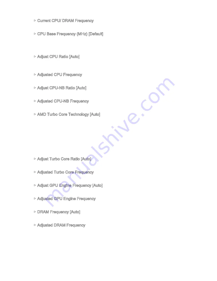
Current CPU/ DRAM Frequency

These items show the current frequencies of installed CPU and Memory. Read-only.


CPU Base Frequency (MHz) [Default]

Sets the CPU Base clock. You may overclock the CPU by adjusting this value. 

Please note that overclocking behavior and stability is not guaranteed. This item 

appears when the installed processor supports this function. 


Adjust CPU Ratio [Auto]

Sets the CPU ratio that is used to determine CPU clock speed. This item can only be 

changed if the processor supports this function.


Adjusted CPU Frequency 

Shows the adjusted CPU frequency. Read-only.


Adjust CPU-NB Ratio [Auto]

Sets the CPU-NB ratio that is used to determine CPU-NB clock speed.


Adjusted CPU-NB Frequency 

Shows the adjusted CPU-NB frequency. Read-only.


AMD Turbo Core Technology [Auto]

Base on AMD Turbo Core Technology, part of CPU core ratio may pop down for 

providing more performance headroom for active CPU core, even AMD Cool’n’Quiet 

Technology is Disabled.
[Auto] 

Turbo Core Technology will linked to AMD Cool’n’Quiet 

Technology.

[Enabled] 

Enables this function.

[Disabled] 

Disables this function.


Adjust Turbo Core Ratio [Auto]

Specifies the Turbo Core frequency multiplier.


Adjusted Turbo Core Frequency

Shows the adjusted Turbo Core frequency. Read-only.


Adjust GPU Engine Frequency [Auto]

Adjust GPU Engine Frequency.


Adjusted GPU Engine Frequency

Shows the adjusted GPU Engine frequency. Read-only.


DRAM Frequency [Auto]

Sets the DRAM frequency. Please note the overclocking behavior is not guaranteed.


Adjusted DRAM Frequency

Shows the adjusted DRAM frequency. Read-only.

Summary of Contents for A68HI ACSeries

Page 1: ...anced AMD FM2 FM2 processor the A68HI AC A68HI Series motherboards deliver a high performance and professional desktop platform solution Layout Top LAN Jack Bottom USB 3 0 ports Top 1 PS 2 combo port Bottom 2 USB 2 0 ports DVI port Top VGA port Bottom HDMI port JUSB2 JUSB1 SATA1 JFP2 M2_PCIE1 JFP1 JTPM1 JPWR1 DIMM1 DIMM2 PCI_E1 JPWR2 JAUD1 CPUFAN1 SYSFAN1 JCI1 SATA3 SATA2 SATA4 T Line In M Line Ou...

Page 2: ...phics 1x VGA port supporting a maximum resolution of 1920x1200 60Hz 24bpp 1x DVI D port supporting a maximum resolution of 2560x1600 60Hz 24bpp 1920x1200 60Hz 24bpp 1x HDMI port supporting a maximum resolution of 4096x2160 24Hz 36bpp 3840x2160 30Hz 36bpp 1920x1200 120Hz 36bpp and 1920x1200 60Hz 36bpp Only be supportted when using an FM2 processors Storage AMD A68H Chipset 4x SATA 6Gb s ports Suppo...

Page 3: ... 2x USB 3 0 ports 1x VGA port 1x DVI D port 1x HDMI port 1x LAN RJ45 port 3x audio jacks Internal Connectors 1x 24 pin ATX main power connector 1x 4 pin ATX 12V power connector 4x SATA 6Gb s connectors 1x USB 2 0 connector supports additional 2 USB 2 0 ports 1x USB 3 0 connector supports additional 2 USB 3 0 ports 1x 4 pin CPU fan connector 1x 4 pin system fan connector 1x Front panel audio connec...

Page 4: ...nk Yellow Linked Blinking Data activity Speed LED Off 10 Mbps connection Green 100 Mbps connection Orange 1 Gbps connection A68HI AC A68HI PS 2 Mouse Keyboard VGA LAN HDMI USB 3 0 USB 2 0 DVI D Antenna Connector Line In Line Out Mic PS 2 Mouse Keyboard VGA LAN HDMI USB 3 0 USB 2 0 DVI D Line In Line Out Mic ...

Page 5: ...old arrow of the APU The gold arrow should point as shown in the picture The APU can only fit in the correct orientation 3 If the APU is correctly installed the pins should be completely embedded into the socket and can not be seen Please note that any violation of the correct installation procedures may cause permanent damages to your motherboard 4 Press the APU down firmly into the socket and cl...

Page 6: ...n the lever 9 Attach the APU Fan cable to the APU fan connector on the motherboard Important While disconnecting the Safety Hook from the fixed bolt it is necessary to keep an eye on your fingers because once the Safety Hook is disconnected from the fixed bolt the fixed lever will spring back instantly Confirm that the APU cooler has formed a tight seal with the APU before booting your system Plea...

Page 7: ...ry modules are not interchangeable with DDR2 and the DDR3 standard is not backward compatible Always install DDR3 memory modules in DDR3 DIMM slots To ensure system stability memory modules must be of the same type and density in Dual Channel mode ...

Page 8: ...r o u n d 6 5 V 1 9 G r o u n d 7 G r o u n d 2 2 5 V 1 0 1 2 V 2 0 R e s 8 P W R O K 2 3 5 V 1 1 1 2 V 2 1 5 V 9 5 V S B 2 4 G r o u n d 1 2 3 3 V JPWR1 4 1 2 V 2 G r o u n d 3 1 2 V 1 G r o u n d JPWR2 Important Make sure that all the power cables are securely connected to a proper ATX power supply to ensure stable operation of the motherboard JAUD1 Front Panel Audio Connector This connector all...

Page 9: ... drives be screwed down into the case Refer to the manual that came with your computer case or your SATA device for further installation instructions Please do not fold the SATA cable at a 90 degree angle Data loss may result during transmission otherwise SATA cables have identical plugs on either sides of the cable However it is recommended that the flat connector be connected to the motherboard ...

Page 10: ... Fan Control with liner mode The Command Center utility can be installed to automatically control the fan speeds according to the CPU s and system s temperature If there are not enough ports on the motherboard to connect all system fans adapters are available to connect a fan directly to a power supply Before first boot up ensure that there are no cables impeding any fan blades JTPM1 TPM Module Co...

Page 11: ...ortant On the connectors coming from the case pins marked by small triangles are positive wires Please use the diagrams above and the writing on the optional M Connectors to determine correct connector orientation and placement The majority of the computer case s front panel connectors will primarily be plugged into JFP1 JUSB1 USB 2 0 Expansion Connector This connector is designed for connecting h...

Page 12: ...3 _ R X _ D N 1 7 U S B 3 _ R X _ D P 1 6 G r o u n d 1 5 U S B 3 _ T X _ C _ D N 1 4 U S B 3 _ T X _ C _ D P 1 3 G r o u n d 1 2 U S B 2 0 1 1 U S B 2 0 Important Note that the VCC and GND pins must be connected correctly to avoid possible damage To use a USB 3 0 device you must connect the device to a USB 3 0 port through an optional USB 3 0 compliant cable M2_PCIE1 M 2 Key E Slot This M 2 port ...

Page 13: ...ata 1 1 Important You can clear the CMOS RAM by shorting this jumper while the system is off Afterwards open the jumper Do not clear the CMOS RAM while the system is on because it will damage the motherboard PCI_E1 PCIe Expansion Slots The PCIe slot supports the PCIe interface expansion card PCIe 3 0 x16 Slot Important When adding or removing expansion cards always turn off the power supply and un...

Page 14: ... failure booting due to inappropriate BIOS configuration Entering BIOS Setup Power on the computer and the system will start the Power On Self Test POST process When the message below appears on the screen please DEL key to enter BIOS Press DEL key to enter Setup Menu F11 to enter Boot Menu If the message disappears before you respond and you still need to enter BIOS restart the system by turning ...

Page 15: ...u display BIOS menu selection Language Virtual OC Genie Button OC Menu Important Overclocking your PC manually is only recommended for advanced users Overclocking is not guaranteed and if done improperly can void your warranty or severely damage your hardware If you are unfamiliar with overclocking we advise you to use OC Genie for easy overclocking ...

Page 16: ...sted CPU NB Frequency Shows the adjusted CPU NB frequency Read only AMD Turbo Core Technology Auto Base on AMD Turbo Core Technology part of CPU core ratio may pop down for providing more performance headroom for active CPU core even AMD Cool n Quiet Technology is Disabled Auto Turbo Core Technology will linked to AMD Cool n Quiet Technology Enabled Enables this function Disabled Disables this fun...

Page 17: ...ing memory timing If it occurs please clear the CMOS data and restore the default settings Refer to the Clear CMOS jumper button section to clear the CMOS data and enter the BIOS to load the default settings DRAM Voltage Auto Sets DRAM voltage If set to Auto BIOS will set DRAM voltage automatically or you can set it manually Spread Spectrum Enabled This function reduces the EMI Electromagnetic Int...

Page 18: ... by pressing F4 Read only CPU Technology Support Press Enter to enter the sub menu The sub menu shows what the key features does the installed CPU support Read only MEMORY Z Press Enter to enter the sub menu This sub menu displays all the settings and timings of installed memory You can also access this information menu at any time by pressing F5 DIMM1 2 Memory SPD Press Enter to enter the sub men...

Page 19: ...en the CPU enters C6 state all cores will save architectural state and reduce core voltages to zero volts Wake up the CPU from C6 state will take a lot longer Disabled Disables this function Power Policy Mode Sets the NB P state Performance Disables the NB P state High NB frequency is fixed for optimum performance Battery Life Enables the NB P state NB frequency will be changed dynamically cTDP Au...

Reviews: