INSTALLATION INSTRUCTIONS
M S D I G N I T I O N
• w w w . m s d i g n i t i o n . c o m • ( 9 1 5 ) 8 5 7 - 5 2 0 0 • FA X ( 9 1 5 ) 8 5 7 - 3 3 4 4
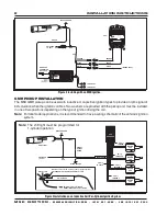
GMR PICKUP INSTALLATION
The MSD GMR pickup can be used with inductive or capacitive ignition types to provide an rpm signal of
30% duration when the ignition coil fires. Two washers are provided with the pickup and must be installed
in one of two positions depending on the type of ignition driving the coil.
Note: For late model applications, it is recommended to have a wiring schematic of the vehicle’s ignition
system.
BLACK GROUND
GMR PICKUP
RED
GREEN
SWITCHED
12 VOLT
SIGNAL
OUTPUT
GMR PICKUP
NOTE: The brass screw must be used for proper operation.
PRIMARY COIL (+) WIRE OR
DIESEL INJECTOR 12 VOLT WIRE
WASHER MUST BE ON TOP OF METAL TAB
METAL TAB
COIL
HARNESS
IGNITION
COIL
IGNITION
COIL
IGNITION
COIL
IGNITION
COIL
COIL (+)
12 VOLTS
COIL (-)
TRIGGER 4
COIL (-)
TRIGGER 3
COIL (-)
TRIGGER 2
COIL (-)
TRIGGER 1
GMR PICKUP
GREEN
SHIFT LIGHT
BLACK GROUND
UP
MODE
DOWN
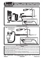
Note: The shift light must be programmed for
1-cylinder operation.
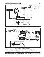
Figure 3 Installation on an Inductive Coil-Per-Cylinder Ignition System.
Figure 2 Installing with an MSD Ignition.
MAGNETIC
CONNECTOR
NOT USED
TO BATTERY
WHITE
BLACK
ORANGE
WHITE
BLACK
ORANGE
RED
TO BATTERY
BLACK
TRIGGER INPUT
RED
RED
SWITCHED
12 VOLT
GREEN
BLACK GROUND
UP
MODE
DOWN
COIL


