MSC CXB-6S, CXB-6SI, C6B-7S
Rev. 1.2
Heat sink mounting instructions
5 / 5
Step 4:
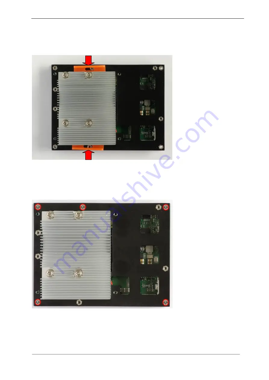
THE MOST IMPORTANT STEP
– Carefully remove the two orange-coloured transportation locks
and at the same time holding the heat sink, so that it does not suddenly hit the CPU die, due to the spring
tension. If the heat sink is released suddenly, it could cause damage to the sensitive ceramic die.
As long as the transportation locks are not removed, there is a gap between CPU die and cooling element
–
the CPU cannot then be cooled!
The transportation locks have to be inserted again whenever the CPU module is removed from the
baseboard. This is necessary in order to prevent the printed circuit board from flexing due to the spring
tension.
Step 5:
Mount the MSC CXB-6S module on the baseboard and fix it securely with five screws as shown
below. Please note, that these screws are not provided in the delivery, because there exist different
mechanical implementation options like stacking height of COM Express receptacles on the customers
carrier board.
Step 6:
If applicable, mount the fan kit and connect it to the appropriate connector. The fan has to blow
downwards onto the module, in order to ensure sufficient air flow, to keep the module cool.
NOTE:
The grey heat conducting pads are phase change material and intended for one-time mounting only. If
you need to remove the heat sink for service purposes and want to reuse it, the wax-like material must be
spread over the full die surface before re-mounting the heat sink (see above, paragraph 2).


