background image


11                                                                                                                              Version 1.0 

Marine computer monoblock  
MVPC-хх04, MVPC-хх05, MVPC-хх06, MVPC-хх07 

5) Wall mounting with a non-adjustable bracket (see figure 7) ensures mounting 

on a surface using brackets and a mounting kit of metal ware.  


Figure 7 – Wall mounting 


1.3.2


General description 

The  Product  is  manufactured  in  metal  casing,  where  a  power  connector,  audio 

ports,  video  ports,  peripheral  interfaces,  local  network  ports  are  generally  located.  Con-
nectors are standard, see figure 8 (Layout of the Product's connectors may vary from the 
specified ones). 

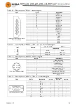
For the description of connectors, see table 7. Electrical connectors pinouts are rep-

resented in tables 


8–18. 

Summary of Contents for MVPC-04 Series

Page 1: ...NPK MORSVYAZAVTOMATICA 26E Kibalchicha str 192174 St Petersburg Russia info unicont com www unicont com Phone 7 812 622 23 10 Fax 7 812 362 76 36 Marine computer monoblock MVPC хх04 MVPC хх05 MVPC хх06 MVPC хх07 Operating Manual ...

Page 2: ...s 19 1 5 Marking and sealing 19 1 6 Packaging 19 2 INTENDED USE 20 2 1 Operational limitations 20 2 2 Preparation for the Product operation 20 2 3 Usage of the Product 21 3 TECHNICAL SERVICE OF THE PRODUCT 22 3 1 General instructions 22 3 2 Safety features 22 3 3 Maintenance routine 22 3 4 Preservation 23 4 CURRENT REPAIR OF THE PRODUCT 24 4 1 General instructions 24 4 2 Safety features 24 4 3 Сur...

Page 3: ...d for the Product s correct and safe operation intended use technical service current repair as well as disposal information for its components Only those who have read operational documentation shall be permitted to oper ate with the Product Only those who have had general education in the area of electronic devices and read operational documentation shall be permitted to provide the Product s se...

Page 4: ... tables 1 6 Table 1 Technical specifications of the MVPC хх04 Parameter MVPC 1204 MVPC 1504 MVPC 1704 MVPC 1904 MVPC 2104 Value Screen diagonal 12 1 15 17 19 21 3 Screen format 4 3 5 4 4 3 Screen resolution 1024х768 1280х1024 1600х1200 Viewable area mm 245х184 304х228 337х270 376х301 432х324 Viewing angle vertical standard brightness 80 80 70 80 80 80 89 89 89 89 high brightness 80 80 70 80 70 70 ...

Page 5: ...to 55 Temperature limit С 60 to 70 Dynamics no yes The monoblocks may be delivered with non standard diagonals One of available options Brightness may differ depending on a particular order Table 3 Technical specifications of the MVPC хх06 Parameter MVPC 1206 MVPC 1506 MVPC 1706 MVPC 1906 MVPC 2106 Value Screen diagonal 12 1 15 17 19 21 3 Screen format 4 3 5 4 4 3 Screen resolution 1024х768 1280х1...

Page 6: ... VAC 110 VAC 24 VDC 12 VDC 220 VAC 110 VAC 24 VDC Protection degree IP22 IP56 front side IP22 other surfaces Type of connectors one out of available options standard protected Operating temperature С 15 to 55 Temperature limit С 60 to 70 Dynamics no yes The monoblocks may be delivered with non standard diagonals One of available options Brightness may differ depending on a particular order Table 5...

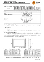
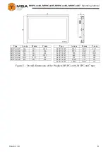
Page 7: ...yPort 1 pc SATA 1 pc Only for MVPC хх04 MVPC хх05 4 pcs for MVPC хх06 MVPC хх07 type 1 2 3 Products overall dimensions depending on the diagonal are represented in figures 1 and 2 Notes 1 Figures 1 and 2 show overall dimensions of the Products casings not includ ing a set of mounting brackets 2 Overall dimensions in figures 1 and 2 are informative and may differ from particular Product design depe...

Page 8: ...9 5 347 5 93 5 MVPC 1206 302 5 251 100 MVPC 2307 567 5 364 5 102 MVPC 1506 362 302 103 MVPC 2407 590 419 5 108 5 MVPC 1706 395 348 105 5 MVPC 2707 662 426 5 100 MVPC 1906 430 5 375 5 103 MVPC 3207 759 478 102 MVPC 2106 492 401 109 MVPC 4207 1000 611 112 MVPC 4607 1092 5 663 5 112 Figure 2 Overall dimensions of the Products MVPC хх06 MVPC xx07 type ...

Page 9: ...l more than 21 vibra tion isolators are provided Types of mounting are shown in figures 3 7 Caution While mounting provide 160 mm free space from the detachable con nection to connect the Product 1 Panel mounting with outside fasteners see figure 3 ensures fastening from the front panel using mounting kit of metal ware Figure 3 Panel mounting with outside fasteners 2 Panel mounting with inside fas...

Page 10: ...ng on a surface using adjustable brackets nut handles and a mounting kit of metal ware Figure 5 Desk top mounting with an adjustable bracket 4 Wall mounting with an adjustable bracket see figure 6 ensures mounting on a surface using adjustable brackets nut handles and a mounting kit of metal ware Figure 6 Wall mounting with an adjustable bracket ...

Page 11: ... Figure 7 Wall mounting 1 3 2 General description The Product is manufactured in metal casing where a power connector audio ports video ports peripheral interfaces local network ports are generally located Con nectors are standard see figure 8 Layout of the Product s connectors may vary from the specified ones For the description of connectors see table 7 Electrical connectors pinouts are rep rese...

Page 12: ...n of the Product s connectors N Name Description Type 1 XPn 8 To connect AC voltage 220 V 50 Hz C13 XPn 9 To connect AC voltage 110 V 50 Hz C13 2 XSn 10 To connect DC voltage 24 V C14 XSn 11 To connect DC voltage 12 V C14 3 XSn 1 To connect VGA DB 15F 4 XSn 4 To connect HDMI HDMI 5 XPn 15 To connect common audio РС10ТВ 6 XSn 12 To connect audio input 3 5 jack XSn 13 To connect audio output speaker...

Page 13: ... recycle bin connection for SSD SATA Note n ordinal number of same type connectors For example if the device has 2 USB interfaces they are marked as XS1 25 XS2 25 Table 8 Description of XSn 25 connector pins Type Pin Description view from connection side 1 5 V VCC 2 data D 3 data D 4 GND USB 3 0 view from connection side 1 VCC 2 D 3 D 4 GND 5 TX 6 TX 7 GND_DRAIN 8 RX 9 RX Table 9 Description of XS...

Page 14: ...Sn 12 XSn 13 XSn 14 connectors pins Type Pin XSn 12 XSn 13 XSn 14 Description 1 GND GND 2 LINE_R MIC_VCC 3 LINE_L MIC_IN Table 12 Description of XPn 15 connector pins Type Pin Description view from soldering side 1 Common GND 2 Lin right Line_R 3 Lin left Line_L 4 common GND 5 In micr Mic_In 6 Micr power Mic_VCC 7 Common GND 8 Aud out right EAR_R 9 Aud out left EAR_L 10 display Table 13 Descriptio...

Page 15: ...green 4 MDI 2 blue 5 MDI 2 white blue 6 MDI 1 green 7 MDI 3 white brown 8 MDI 3 brown Table 17 Description of XSn 5 XSn 50 connector pins Type Pin Description Display Port mini Display Port pinout of unit from side of cable connection pinout of unit from side of cable connec tion 1 3 Main Link Lane 0 2 1 GND Земля 3 5 Main Link Lane 0 4 9 Main Link Lane 1 5 7 GND Земля 6 11 Main Link Lane 1 7 15 M...

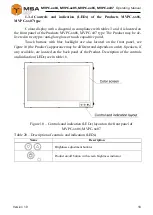
Page 16: ...5 В Power 16 5 В Power 17 GND Earth 18 GND Earth 19 GND Earth 20 12 В Power 21 12 В Power 22 12 В Power 1 3 3 Controls and indication of MVPC хх04 MVPC хх05 type Colour display with a diagonal in compliance with tables 1 and 2 is located on the front panel of the Products MVPC хх04 MVPC х05 type The Product may be de livered in two types anti glare glass or touch capacitive panel Controls indicati...

Page 17: ...ble 19 Description of the controls and indication LEDs N Name Description 1 Reset button Button restarts the product 2 Power button Button switches on off the product 3 Display brightness LED LED shows display brightness status 4 Brightness adjust ment knob dimmer Knob ensures screen backlight adjustment 5 USB Provides connection of external USB devices 6 Speakers 7 Control and indication LEDs pan...

Page 18: ...touch capacitive panel Touch buttons with blue backlight are also located on the front panel see figure 10 the Product s appearance may be different and depends on order Speakers if any available are located on the back panel of the Product Description of the controls and indication LEDs see in table 18 Figure 10 Controls and indication LEDs layout on the front panel of MVPC хх06 MVPC хх07 Table 2...

Page 19: ... cohol 0 05 l To soak cloth while removing contamination Varnish 0 05 kg To cover surfaces of the product in case of paint coating damage Abrasive cloth 0 06 х 0 06 m To polish surfaces of the product in case of paint coating damage 1 5 MARKING AND SEALING The Product has a marking tag for connectors and nameplate where a user can find a serial number date of manufacturing weight protection degree...

Page 20: ...he technical rules for operation of electric installation and Safety rules for operation of electric installation while testing electrical circuits and insulation resistance 2 2 2 Method of the visual check Before switching the Product on the staff shall observe visually the cable integrity and initial position of the controls on the front panel clean front panels from dust and dirt by clean soft ...

Page 21: ...disconnect power cable from the Product 2 3 USAGE OF THE PRODUCT The Product is delivered with pre configured software in accordance with the order from the manufacturing plant and it is ready to be used After switching the Product on make sure that power supply indication is func tioning and graphic data to be displayed on the screen are correct and accomplish prop er quality Check touch screen o...

Page 22: ...ROUTINE The list of works for all types of the Technical service is given in table 22 Mainte nance routine procedure is given in the checklists CL represented in tables 23 24 Table 22 The list of the TS works CL Name of work TS type ТS 1 ТS 2 1 Visual check of the Product 2 Product operation test Notes work is obligatory work is not required Table 23 CL 1 Visual check To be done Routine Man hours ...

Page 23: ...are visible 1 person 5 mins Table 24 CL 2 The Product s operation test To be done Routine Man hours per 1 Product Check indication and picture on the computer screen 1 Switch the Product on picture shall be in accordance with the pre configured software 2 The Product s indication shall be in order and work 1 person 5 mins Check ports 1 Check operation of any device connected to the Prod uct 2 Chec...

Page 24: ...is STRICTLY PROHIBITED Put a poster DO NOT switch on Under Operation when power supply switch is in OFF position Installation commissioning and repair works are PROHIBITED in the room where less than 2 people present 4 3 СURRENT REPAIR The service personnel can provide repair works as given in table 25 All other defects shall be carried out only by the Manufacturer s specialists or the Manufacture...

Page 25: ...he re quired storage conditions 5 to 40 С with the concentration of dust oil moisture and aggressive impurities in the air within the required limits for the working areas of production facilities After storage or transportation of the Product below 10 С it must be un packed only in heated premises and left in normal climate conditions for 12 hours be forehand ...

Page 26: ...air transportation in sealed and heated compartments sea transportation in dry service premises The Product must be transported in compliance with transportation rules appli cable for each means of transport During loading unloading operations and transportation the requirements indi cated on warning labels on the boxes packaging must be observed and no impacts are permitted since they can affect ...

Page 27: ... authorities You can also send an over age equipment unit to the manufacturer for its further disposal Proper disposal of Product components allows avoiding possible negative envi ronmental and health impacts and it also allows for proper restoration of components with substantial energy and resources saving During operation and upon completion of its service life the equipment is not hazardous fo...

Page 28: ... of operation conditions damage claims are not considered by the Manufacturer More information about warranty terms you can find on the official site of NPK Morsvyazavtomatica LLC section Support Address and contacts of the Manufacturer s service centre NPK Morsvyazavtomatica LLC 26E Kibalchicha str 192174 St Petersburg Russia Tel 7 812 602 02 64 8 800 100 67 19 fax 7 812 362 76 36 e mail service ...

Reviews: