background image


1


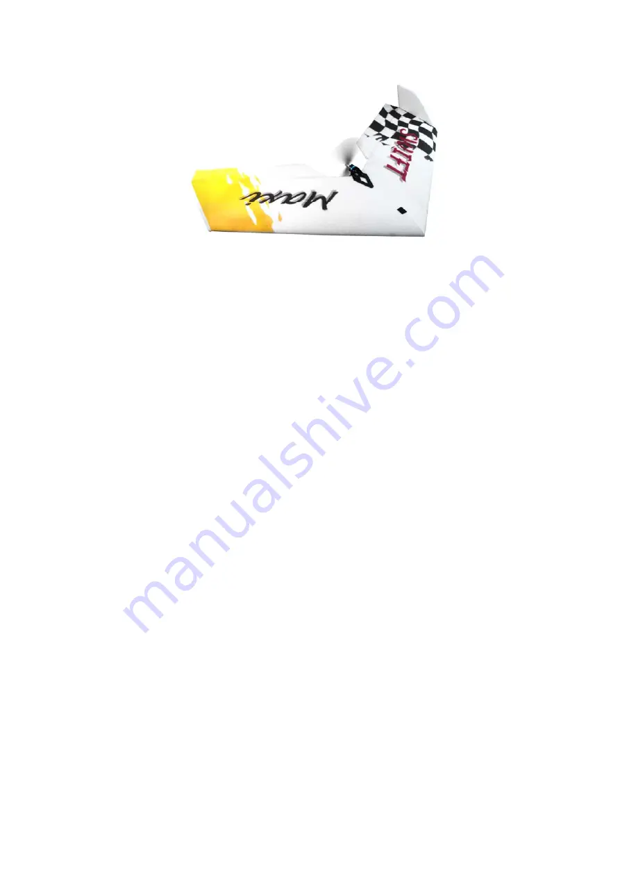
SWIFT MAXI 


Stavební návod 


Assembly Instructions 


Technical data

 
   Wingspan: 

  1380 

mm 

   Total 

weight: 

  900-1200 

   Wing 

surface:  56 

dm

2


   Motor:   EM 

400/ 

EM 

540 


Power source: 


3S Li-Pol 2400 / 3S2P Li-Pol 2400 

   Controlled 

functions: Elevator, 

Aileron, 

Throttle, 


Elevon mix needed 

Summary of Contents for SWIFT MAXI

Page 1: ... Assembly Instructions Technical data Wingspan 1380 mm Total weight 900 1200 g Wing surface 56 dm2 Motor EM 400 EM 540 Power source 3S Li Pol 2400 3S2P Li Pol 2400 Controlled functions Elevator Aileron Throttle Elevon mix needed ...

Page 2: ...ihedral Elevon Steering element fulfills aileron and elevator function Used on delta planes Assembly steps RC set up Switch on the transmitter set up the proper mix for delta planes set trims to neutral position Put simple horns on the servos the horns are perpendicular to the lower wing surface Make a cut in the wing to place antenna in if the antenna is longer than the half of the wing make the ...

Page 3: ...f and using CA glue fix the motor bed onto the top center side of the wing Before gluing coarsen the surface of the motor bed Steering elevon horn Put the horn on the elevons in such a manner see picture on right side and the hole for the pushrod is in perpendicular position over the elevon axis of rotation Cut holes for servos as see picture on right side Rudder assembly Glue the rudders to the e...

Page 4: ...tention the elevon rotates on upper wing surface It might be needed to cut a dent in the wing to allow free horns movement in maximal negative deflection Put the servos into the proper holes see picture and fix it by the fiber tape Cut holes for receiver regulator and for bateries depend on power motor if you want to use EM400 with one baterie 3xLi Pol 2400 mAh cut only one hole For EM 540 with tw...

Page 5: ... comparison to standard planes Pic 7 COG position Final in flight balancing Throw the model similarly to a boomerang holding it on leading edge Model should immediately fly Climb higher and adjust the trims to perform final COG check Let the model decline with approx 30 angle and put the sticks into neutral position If the angle tends to increase and model declines faster the COG is too much in ba...

Reviews: