MRMC MRMC-1479-00 Quick Start Manual Download Page 14

Titan Quick Start Guide

9

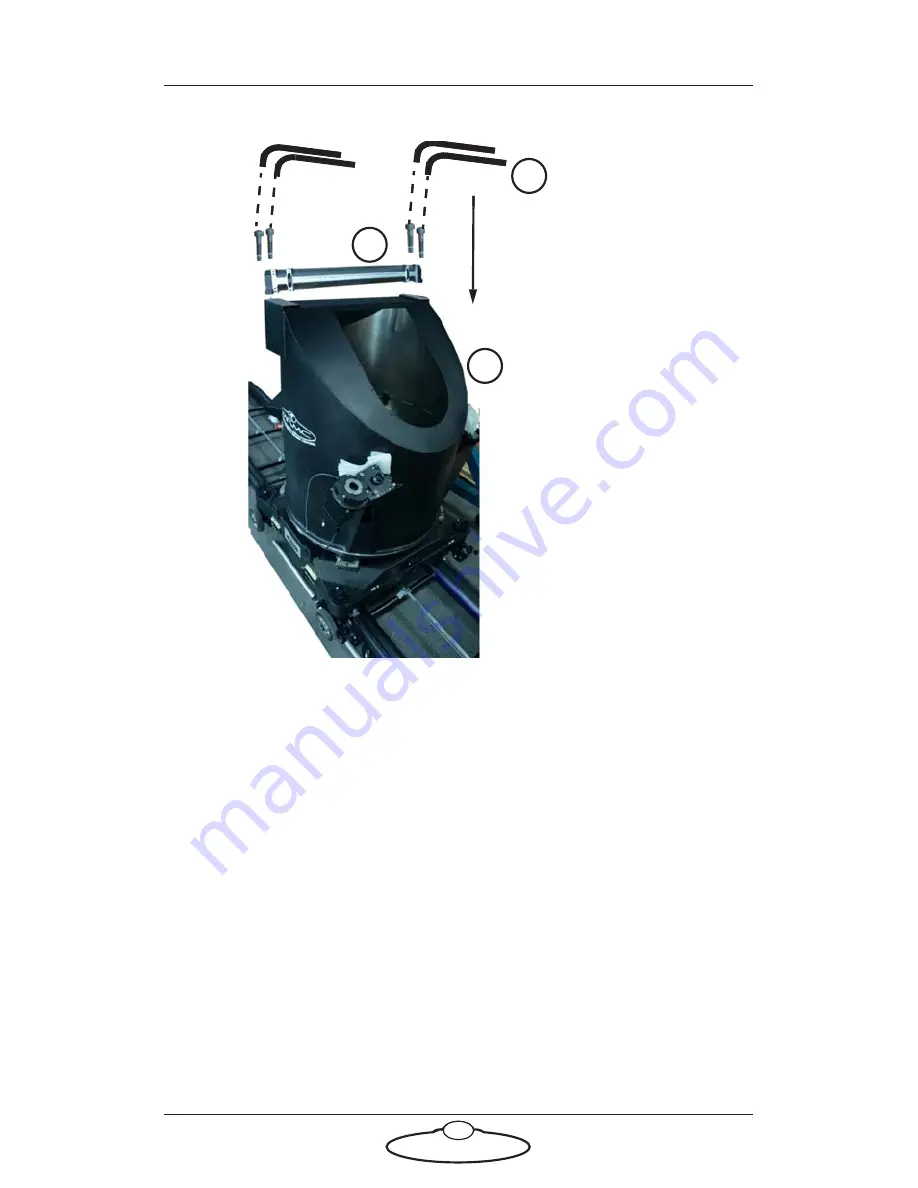
Mounting the main shaft

1.

Remove the inspection cover from the turret.

2.

Place the main shaft on top of the turret aligning the screw slots.

3.

Insert and tighten the two bolts on each side of the main shaft to 
secure it to the turret. The front bolts should have nylocs 
underneath after bolting in place.

1

2

3

Summary of Contents for MRMC-1479-00

Page 1: ...S IN CAMERA ROBOTICS CRANES AND RIGS BROADCAST HEADS DSLR PRODUCT PHOTOGRAPHY RENTALS Titan WORLD S LARGEST TELESCOPIC MOTION CONTROL ARM Quick Start Guide Product code MRMC 1479 00 Part number MRMC 1...

Page 2: ...ocument is accurate and up to date Mark Roberts Motion Control continuously strives to improve their products and may make changes to the hardware firmware and software described in this document Mark...

Page 3: ...iii...

Page 4: ...the driver box 11 Mounting the Titan main arm 12 Mounting the counter weight mounting bars 13 Mounting the nose 13 Adding the counter weights 14 Mounting the bucket 15 Mounting the head 17 Connecting...

Page 5: ...Titan Quick Start Guide iv...

Page 6: ...ead or Slimline head on which you mount your video camera A Windows PC running Flair Motion Control Software An RT 14 interface box which handles the connections between the PC and the Titan rig Addit...

Page 7: ...peed high acceleration industrial grade robots which can cause severe injuries such as Titan Unlike traditional motion control equipment Titan arm can extend with speed in the blink of an eye too fast...

Page 8: ...Volt three phase power supply five wire including Neutral and Ground and can not be configured to run on less The computer stack that controls Titan that is the desktop computer and the power supply...

Page 9: ...barriers and light guards curtains Keep stands lights and accessories out of the No Go Zone if possible If not possible then try to take as much care with their positioning and the motion of the rig a...

Page 10: ...the equipment dry The system has not been made weatherproof Do not use with wet hands Always run moves only when standing within easy reach of the emergency stop Always loudly and clearly indicate to...

Page 11: ...lly warning the operator Any such person is to have a clear escape route to allow them to move safely away from the robot During use repeatedly check the rig mounting points cables camera mount access...

Page 12: ...page 9 3 Mount the lift ball screws page 10 4 Mount the power supply unit and the driver box page 11 5 Mount the Titan main arm page 12 6 Mount the counter weight mounting bars page 13 7 Mount the nos...

Page 13: ...3 Lower the turret onto the base Ensure that the slip rings line up with the motor connectors 4 Press the four turret bolt retainers all the way into the turret and tighten the bolts down into the bas...

Page 14: ...pection cover from the turret 2 Place the main shaft on top of the turret aligning the screw slots 3 Insert and tighten the two bolts on each side of the main shaft to secure it to the turret The fron...

Page 15: ...box Ensure that the hole lines up with the dowel on the gear box housing 2 Tighten the four bolts on the belt box to hold it in place 3 Add the two brace pieces to further secure the lift ball screws...

Page 16: ...Titan Quick Start Guide 11 Mounting the Power Supply Unit and the driver box 1 Put the bracket on the two mounting hooks on the rear of the turret 2 Lift the PSUs and place them in the bracket...

Page 17: ...turret so the brackets on the main shaft face up 2 Using a gantry lift place the retracted arm without mounting bars onto the brackets on the main shaft 3 Insert and tighten the eight bolts that hold...

Page 18: ...and insert the counter weight mounting bars in the two slots on each side 2 Release the clamp and tighten the single bolt to secure the counter weight mounting bars Mounting the nose 1 2 1 Lift nose...

Page 19: ...counter weight mounting bars These should be about 16 when using the Ulti head and 20 when using the Guinness head 2 Lower the clamp and tighten the nut to secure the counter weights Note Ensure that...

Page 20: ...r arm into the nose These are the power connector the encoder connector for the outer arm and the limit switches 3 Retract the overcenter lock mesh bracket and secure it by inserting an allen key into...

Page 21: ...e 16 5 Remove the allen key and pull the lever to lock the gear into mesh You will need to reach in to the lever from below the nose 6 Replace the safety bolt Tip Swing the bucket slightly to ensure t...

Page 22: ...Titan Quick Start Guide 17 Mounting the head Key Slot Example Ulti Head Mount the head to the bucket using the three bolts making sure that the key on the head fits into the slot in the bucket...

Page 23: ...Titan Quick Start Guide 18 Connecting the cables Picture of umbilical base connections Picture of PSU Turret Titan Arm connections Milo Base Umbilical cable wrap...

Page 24: ...s 1 Attach the cable to the Limit and Datum connector 2 Attach the brake and speed sensor cable to the connector and tighten it 3 Attach the lift motor cable to the lift motor 4 Attach the break and s...

Page 25: ...Titan Quick Start Guide 20 Connections to the slip ring base on the Ulti head Attach the cables to the head and camera Here is an example of the cables attached to the Ulti head...

Page 26: ...ct way around for the track 3 Push the rig to the levelled part of the ramp ups and whilst in the position push the four track bearings under the four corners of the Milo base making sure that all fou...

Page 27: ...ake sure the area alongside the track is clear so that the umbilical cable doesn t catch on anything when Milo drags it alongside the track 6 Attach the track motor pinch wheel on the underside of Mil...

Page 28: ...hold the assembly in place on the track motor 4 Hand tighten the pinch wheel adjustment bolt so that the rubber wheel presses firmly against the smooth side of the rack This holds the track motor gear...

Page 29: ...pow er to Tita n arm D a t a l i n k I n p u t To Tita n arm Sin gle pha se pow er to PSU EST OP RO OT ES TO P Pow er for Dri ver Box 1 TR AC K LIF T E X T E N D A N G L E Vid eo cab les to the hea d...

Page 30: ...ernet Power Supply 400 Volt 3 phase 5 wire including Neutral and Earth VIDEO SIGNALS Power Supply 120 240 Volts hub 5V Flair dongle cable in USB port RT 14 Hand Held Box Ethernet for Camera ETHERNET P...

Page 31: ...powering up step 3 and 4 6 On the Flair PC start the Flair application by double clicking on the Flair icon on the Desktop Flair automatically loads the relevant firmware into all attached axis boards...

Page 32: ...ed Track limits Lens Control Motor limits if using external LCMs Milo Titan start up summary 1 Secure the area 2 Release the E stop on the rig 5 Turn switches on the PSU 5 Switch on the Flair PC and R...

Page 33: ...e to reset the soft limits to reach the transport position or by moving the arm manually 2 In the Flair software disengage all axes 3 Press down the E stop button on the computer stack 4 Close the Fla...

Page 34: ...oad camera and head 50 Kg Power requirements 400 Volts 3 phase earthed grounded 7KW Temperature range 0 45 C 32 113 F Humidity tolerance 0 to 85 relative humidity non condensing Rotate 360 degrees Lif...

Page 35: ...Titan Quick Start Guide 30 Notes...

Page 36: ...Titan Quick Start Guide 31 Notes...

Page 37: ...Mark Roberts Motion Control Ltd Unit 3 South East Studios Blindley Heath Surrey RH7 6JP United Kingdom Telephone 44 0 1342 838000 info mrmoco com www mrmoco com...

Reviews: