background image

55 


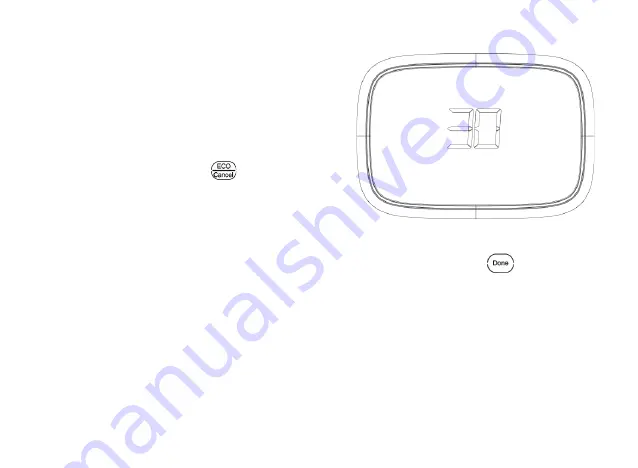
Cleaning Thermostat Screen


The thermostat has touch screen 
interaction. Follow these steps to clean 
the screen without making thermostat 
changes: 
1.  Press and hold the 

  key for 

approximately 3 seconds until the 
screen changes. Th ermostat locks 
out all touch keys for 30 seconds to 
allow for cleaning. See Fig. 2 8. 

2.  Use damp cloth slightly moistened 

with water or house-hold glass 
cleaner to clean the screen.   


Fig.2 8. 

When finished, press 

  key to 

return to the Home Screen and normal 
operation. See Fig.2 9. 

Summary of Contents for MST03

Page 1: ...MRCOOL Universal WiFi Thermostat...

Page 2: ......

Page 3: ...Contents APPLICATION 1 FEATURES 2 SPECIFICATIONS 3 INSTALLATION 5 WIRING 13 POWERING THE THERMOSTAT 30 INSTALLER SETUP 32 OPERATION 44 PROGRAMMING 64 FCC Note 70 TROUBLESHOOTING 72...

Page 4: ......

Page 5: ...ibility precise comfort control and e ortless programming MRCOOL provides temperature control for gas oil electric and heat pumps for up to 3 heating and 2 cooling systems Not only can you remotely mo...

Page 6: ...temperature and humidity Menu driven programming makes setup e ortless Beautiful ergonomic design is smart and sophisticated to match your lifestyle Touchscreen capability Connect to the Internet to m...

Page 7: ...C to 32 C Cooling 50 F to 99 F 10 C to 37 C Operating Ambient Temperature 32 F to 122 F 0 C to 50 C Shipping Temperature 14 F to 140 F 10 C to 60 C Operating Relative Humidity Non condensing IRS 1 5...

Page 8: ...h Cool Indication Show Cool On on the screen when Cool is activated Heat Indication Show Heat On on the screen when Heat is activated Auxiliary Heat Indication Show Aux On on the screen when Auxiliary...

Page 9: ...for your application 3 Installer must be a trained experienced service technician 4 After completing installation use these instructions to check out the product operation Selecting Location Install...

Page 10: ...ed or uncooled areas such as an outside wall behind the thermostat Mounting Means Mounts directly on the wall in the living space using mounting screws and anchors provided Dimensions 1 MRCOOL dimensi...

Page 11: ...7 Fig 1 Thermostat Dimensions in inches mm...

Page 12: ...8 Fig 2 Thermostat back case dimensions in inches mm...

Page 13: ...9 Fig 3 Thermostat cover plate dimensions in inches mm...

Page 14: ...10 Fig 4 Selecting thermostat location...

Page 15: ...on and level the wall plate for appearance only 2 Use a pencil to mark the mounting holes 3 Remove the wall plate from the wall and drill two holes in the wall as marked Gently tap anchors provided in...

Page 16: ...12 Fig 5 Mounting wall plate...

Page 17: ...ble 1 and Fig 6 for terminal designation descriptions Insert wires in the terminal block under the loosened screw See Fig 7 2 Securely tighteneach screw 3 Push excess wire back into the hole 4 Plug th...

Page 18: ...y side of heating system transformer C see Note 2 Common wire from secondary side of cooling system transformer Y Compressor contactor G Fan relay Y2 Second stage cooling O B W see Note 3 Changeover v...

Page 19: ...ace between RC and R If used on a two transformer system remove metal jumper wire between RC and R 2 If thermostat is con gured for a heat pump system con gure changeover valve forcool or heat 3 L ter...

Page 20: ...16 Fig 7 Inserting wires in terminal block IMPORTANT Use 18 gauge thermostat wire...

Page 21: ...SUPPLY PROVIDE DISCONNECT MEANS AND OVERLOAD PROTECTION AS REQUIRED 2 FACTORY INSTALLED JUMPER Fig 8 Typical hookup of conventional single stage heat and cool system with single transformer 1H 1C con...

Page 22: ...R SUPPLY PROVIDE DISCONNECT MEANS AND OVERLOAD PROTECTION AS REQUIRED 2 FACTORY INSTALLED JUMPER Fig 9 Typical hookup of conventional single stage heat and cool system with two transformers 1H 1C conv...

Page 23: ...19 1 POWER SUPPLY PROVIDE DISCONNECT MEANS AND OVERLOAD PROTECTION AS REQUIRED 2 FACTORY INSTALLED JUMPER Fig 10 Typical hookup of heat only system 1H conventional...

Page 24: ...20 1 POWER SUPPLY PROVIDE DISCONNECT MEANS AND OVERLOAD PROTECTION AS REQUIRED 2 FACTORY INSTALLED JUMPER Fig 11 Typical hookup of heat only system with fan 1H conventional...

Page 25: ...21 1 POWER SUPPLY PROVIDE DISCONNECT MEANS AND OVERLOAD PROTECTION AS REQUIRED 2 FACTORY INSTALLED JUMPER Fig 12 Typical hookup of heat only power to open and power to close zone valve system...

Page 26: ...22 1 POWER SUPPLY PROVIDE DISCONNECT MEANS AND OVERLOAD PROTECTION AS REQUIRED 2 FACTORY INSTALLED JUMPER Fig 13 Typical hookup of heat only system with normally open zone valves...

Page 27: ...23 1 POWER SUPPLY PROVIDE DISCONNECT MEANS AND OVERLOAD PROTECTION AS REQUIRED 2 FACTORY INSTALLED JUMPER Fig 14 Typical hookup of cool only system 1C conventional...

Page 28: ...ONNECT MEANS AND OVERLOAD PROTECTION AS REQUIRED 2 FACTORY INSTALLED JUMPER Fig 15 Typical hookup of conventional multi stage two stage heating and two stage cooling in a single transformer system 2H...

Page 29: ...SCONNECT MEANS AND OVERLOAD PROTECTION AS REQUIRED 2 FACTORY INSTALLED JUMPER Fig 16 Typical hookup of conventional multi stage two stage heating and two stage cooling in a two transformer system 2H 2...

Page 30: ...T MEANS AND OVERLOAD PROTECTION AS REQUIRED 2 FACTORY INSTALLED JUMPER 3 O B TERMINAL SET TO CONTROL AS EITHER O OR B IN THE INSTALLER SETUP Fig 17 Typical hookup of single stage heat pump with no aux...

Page 31: ...2 FACTORY INSTALLED JUMPER 3 MUST CONNECT THE 24VAC COMMON WHEN USING L THE TERMINAL IS SHOWN AS EQUIPMENT MONITOR 4 O B TERMINAL SET TO CONTROL AS EITHER O OR B IN THE INSTALLER SETUP Fig 18 Typical...

Page 32: ...D 2 FACTORY INSTALLED JUMPER 3 MUST CONNECT THE 24VAC COMMON WHEN USING L THE TERMINAL IS SHOWN AS EQUIPMENT MONITOR 4 O B TERMINAL SET TO CONTROL AS EITHER O OR B IN THE INSTALLER SETUP Fig 19 Typica...

Page 33: ...D 2 FACTORY INSTALLED JUMPER 3 MUST CONNECT THE 24VAC COMMON WHEN USING L THE TERMINAL IS SHOWN AS EQUIPMENT MONITOR 4 O B TERMINAL SET TO CONTROL AS EITHER O OR B IN THE INSTALLER SETUP Fig 20 Typica...

Page 34: ...e in place between RC and R Two Transformer System Connect the common side of the cooling transformer to the C screw terminal of the thermostat wall plate Remove the metal jumper wire between RC and R...

Page 35: ...31 Fig 21 Mount thermostat to wall plate...

Page 36: ...the Installer Setup 1 See Fig 22 1 Press and release the Key System mode will blink then press and hold the key for approximately 5 seconds until the screen changes Menu numbers will display at botto...

Page 37: ...press key enter submenu Under submenu use or to set parameters See Fig 22 3 Fig 22 3 Note See Tables 2 for the Installer Setup Numbers and Settings 3 Press key to exit and con rm the installer setup...

Page 38: ...u Number Name Settings Notes 0140 MAC and version See MAC and rmware version 0150 Date and time Set calendar date and time 0160 Schedule Options 0 non programmable 1 7 day programmable The schedule se...

Page 39: ...or normally open zone valves 6 cool only conventional 7 2heat 1cool heat pump with auxiliary heat 8 2heat 2cool multistage conventional 9 2heat 1cool multistage conve ntional 10 1heat 2cool multistag...

Page 40: ...at controls fan in heating Only shown if conventional system is selected If heat pump is chosen fan defaults to electric 0190 Changeover Valve O B Terminal Energized in Heating or Cooling Heat Pumps O...

Page 41: ...di erence 4 16 leave mode heating the range of setting temperature 0 5 di erence 0230 Leave mode cooling setting temperature 76 99 leave mode cooling the range of setting temperature 1 di erence 24 37...

Page 42: ...auto changeover 0310 Dead band 2 2 F 1 5 C 3 3 F 2 C 4 4 F 2 5 C 5 5 F 3 C 6 6 F 3 5 C 7 7 F 4 C 8 8 F 4 5 C 9 9 F 5 C Shown only if 0300 is selected 0320 Temperature Indication Scale 0 Fahrenheit fac...

Page 43: ...efault 2F Fahrenheit value is 2 times of centrigrade value 0350 3stage hysteresis 1 F 3 F default 2F Fahrenheit value is 2 times of centrigrade value 0500 Furnace Change Reminder 0 furnace lter remind...

Page 44: ...period 0 Conventional Recovery system starts recovery at programmed time 0540 Number of Periods 2 two periods available Wake and Sleep 4 four periods available Wake Leave Return and Sleep Only shown...

Page 45: ...Stop 40 90 temperature range 1 F increments of heating set point Shown in 1 2 C 0610 Cool Temperature Range Sto p 50 99 temperature range 1 F increments of cooling set point Shown in 1 2 C 0640 Clock...

Page 46: ...after call for heat ends Not shown in Cool Only Systems 0660 Extended Fan On Time Cool 0 No extended fan operation after call for cool ends 90 Fan operation is extended 90 seconds after call for cool...

Page 47: ...F as temperature format 4 5 C 4 5 C C as temperature format 0 F 0 C factory setting 0710 Reset Thermostat 0 No thermostat reset 1 Resets all Installer Setup Options to default values and resets sched...

Page 48: ...44 OPERATION Fig 23 Thermostat Keys Fan Choose fan mode...

Page 49: ...45 Fig 24 Thermostat Display...

Page 50: ...er will display at bottom right corner 2 Press or key to cutover to submenu and press key enter submenu Under submenu use or to set parameters 3 Press key to exit and con rm the user setup or press to...

Page 51: ...Description Settings 0140 See MAC and Version 0150 Date and Time Current calendar date and time 0320 Display temperature in F or C 0 F setting factory setting 1 C setting 0640 Clock Format 12 12 hour...

Page 52: ...cked keypad 0700 Temperature Display O set 3 F 3 F F as temperature format 1 5 C 1 5 C C as temperature format 0 F 0 C factory setting 0710 Reset Thermostat 0 No thermostat reset 1 Resets all Installe...

Page 53: ...setting 2 Press to switch from date to time in the following order year month day hour and minute Press or to adjust the time You can advance the time more quickly by holding the key or key buttons 3...

Page 54: ...peration 2 Press again to select ON or AUTO toggle to re select The selected option blinks 4 Press to save setting or press to exit without saving changes ON Fan is always on AUTO Fan runs only when t...

Page 55: ...de 1 Press to display options 2 Press again to select an option You may need to press two or three times to make a selection the selected option blinks 3 Press to save setting or press to exit without...

Page 56: ...heating or cooling depending on the indoor temperature EMER heat pumps with aux heat Controls auxiliary emergency heat when compressor is locked out Note The AUTO and EMER system settings may not ap...

Page 57: ...e you want the icon Until appears above Time and the Time becomes next scheduled period time 2 Press key to exit and con rm the changes or press to exit without saving changes 3 If you want to exit Ov...

Page 58: ...54 Permanent override Keep user settings permanently 1 Press key once Screen shows Permanent Hold 2 Press or key to adjust temperature you want 3 If you want to exit please press key again...

Page 59: ...Press and hold the key for approximately 3 seconds until the screen changes Thermostat locks out all touch keys for 30 seconds to allow for cleaning See Fig 2 8 2 Use damp cloth slightly moistened wit...

Page 60: ...hen use the cloth to clean the thermostat screen Screen Locks In User or Installer Setup menu 0670 allows you to prevent changes to all of the touchscreen functions In this case all keys are locked an...

Page 61: ...imer To change the reminder interval 1 Press and hold the about3 seconds until screen changes 2 Press or to select the desired interval in days then press to save and exit or press to exit without sav...

Page 62: ...twork Please scan the following code to download MRCOOL Universal App If you get stuck At any point in this procedure restart the thermostat by removing the thermostat from the wall plate wait a few s...

Page 63: ...d WiFi don t connect the hidden internet download MRCOOL Universal 2 Open App and register Fig 31 Fig 32 3 After login press top left corner choose WiFi connection and input the WiFi password DON T pr...

Page 64: ...60 Fig 33 Fig 34 4 Press the key on thermostat screen until the flash Fig 35...

Page 65: ...61 5 Now you can press the connect on app app will show processing and after seconds it will show a successful connection Fig 36 Fig 37...

Page 66: ...62 Note 1 If connected WiFi successfully it will show on the thermostat otherwise it will show 2 Each con guration needs to be nished within 5 minutes otherwise the thermostat will quit con guring...

Page 67: ...at will switch to leave mode You can set the temperature you need under leave mode See the following programming to set the temperature If the Universal Thermostat has been under leave mode press on h...

Page 68: ...Default Program Settings Schedule Period Time Set points Fan Setting Heat Cool Wake 6 00AM 68 F 20 C 78 F 26 C Auto Leave 8 00AM 60 F 16 C 85 F 29 C Auto Return 4 00PM 68 F 20 C 78 F 26 C Auto Sleep 1...

Page 69: ...aken and want your home at a comfortable temperature Leave Period when you are away fromhome and want an energy saving temperature Return Period when you return home and want your home back to a comfo...

Page 70: ...hange See Fig 39 and 40 Fig 39 2 In this case the time will blink press or to adjust the time Press to turn to next setting 3 Then the temperature will start to blink press or to adjust the temperatur...

Page 71: ...r time periods Then press to turn to next day until completing the setting of a week 5 To end program setting press key to exit and con rm the program setting or press to exit without saving changes N...

Page 72: ...s follows 1 Select the program for Monday complete the setting of Monday and press the icon appears on the screen and the icon Will blink that indicates waiting to be selected or skipped Press to sele...

Page 73: ...ostat can reset schedule setup option to default setting Press and hold key for approximately 3 seconds until the screen changes as Fig 41 then release key Now the setting of schedule resets to defaul...

Page 74: ...ncluding interference that may cause undesired operation Note This equipment has been tested and found to comply with the limits for a Class B digital device pursuant to part 15 of the FCC Rules These...

Page 75: ...he user is encouraged to try to correct the interference by one or more of the following measures Reorient or relocate the receiving antenna Increase the separation between the equipment and receiver...

Page 76: ...Check 24VAC between C and R Temperature settings do not change The upper or lower temperature limits were reached Check temperature set points Check Installer Setup Numbers 0600 or 0610 modify as need...

Page 77: ...at minimum o time is activated Wait up to ve minutes for the system to respond Sy stem selection is not set to Heat or Cool Set system selection to correct position System type selection is incorrect...

Page 78: ...ipment is not operating Check wiring Check Installer Setup Number 0170 and make sure correct system type is chosen Verify operation of equipment in System Test mode Fan does not turn on in a call for...

Page 79: ...aller Setup Number 0190 to match the changeover required by the installed heat pump Both the heating and cooling equipment are running at the same time The heating equipment is not a heat pump but the...

Page 80: ...tem Type Installer Setup Number 0170 to match the installed heating and or cooling equipment Heating equipment does not turn o and heat temperature setting is set below room temperature Heating equipm...

Page 81: ...talled equipment Heat On is not in the display System is not set to Heat and or temperature is not above room temperatur e Set the system setting to Heat and set the temperature setting above the room...

Page 82: ...ssor minimum o timer is active Wait up to ve minutes for the cooling or heating heat pump equipment to turn on Screen Locked appears on the screen and the keys do not respond The keypad is locked Chec...

Reviews: