

To test, place the loco on the test track. Select the “Run” mode of your DCC
system and select or acquire address #3. Move up the throttle and the loco
should move forward. Push the light button [F0] and the front headlight should
come on. Change the direction of the loco and the loco should change direction
and the rear headlight (if equipped) should come on. The loco cannot reach full
speed, due to the resistor. If all above occurs, you passed the test. Congratula-
tions!
Do not run the loco for an extended period of time on the test track or
the resistor will overheat.
If your installed decoder does not pass the test, find the problem, correct it and
test it again.
OPERATION
This decoder has start up and shut down feature. You must press any function
key to start up the engine before operating the loco. To shut down the engine
you must bring the loco to idle and then press F8 3 times.
This decoder can also be used in an Electric Type Traction Loco such as Trolley
or GG-1 by turning off diesel sounds. To turn off the diesel prime mover sounds,
program CV #122 with value 0.
If using the MRC Prodigy Advance DCC System, you can use F18 to select
different bells. First use F1 to activate bell. Then use F18 to scroll through 8
different bell sounds. You can use F19 to scroll through 15 different horns.
When using other DCC systems you have to program CV #52 to select bell and
CV #50 to select horn.
There are many more program features available with this decoder. Please refer
to the CV Chart to explore other features of the decoder.
DIESEL SOUNDS CHART
INSTALLATION
It is quite a challenge to install this decoder into an “N” scale diesel locomotive.
You should have some basic electronics knowledge, and some chassis/frame
milling and soldering skills. If you are not sure you can perform this installation by
yourself, you can contact “Aztec Mfg.” Tel: [775] 883-3327, for an aftermarket
chassis.
The body shell, and fuel tank casting must be removed from the chassis, and the
entire frame must be disassembled. Mark the top of the motor with a dab of paint or
permanent marker; remove the original circuit board, motor, driveshafts, bearings,
and trucks.
An area of the fuel tank portion of the frame must be milled out to accommodate the
speaker using a rotary or comparable tool, a wire channel for the speaker wires
should be cut on both frame halves with a cutting disk. Use a small modelers file to
remove any rough or jagged edges from the frame castings.
The speaker wires are coated with a ceramic insulation and are very delicate.
Care should be taken not nick the wires or repeatedly bend them during installation,
as this could damage the insulation, causing a short circuit.
The top portion of each frame half that touches the motor brush tabs
should be insulated with a small piece of clear tape.
The decoder replaces the original circuit board of the locomotive and should fit in
the same location. Assemble one half of the frame first, installing the decoder,
motor, driveshafts, bearings, trucks, and frame spacers. Gently place the other
frame half on top of the completed half, checking clearances and if there is any
binding of the drive mechanism. Correct any trouble spots at this point. Also check
to make sure the motor brush tabs are not touching the frame halves and the clear
tape is correctly positioned at the motor brush tab points to avoid shorting out the
decoder. Now you can install the insulated bolts and nuts to secure both frame
halves together.
Gently route the speaker wires into the channels, fold any excess length of wire
above or next to the decoder and secure with a piece of clear tape.
Re-check installation!!!
If at this point you are satisfied with the mechanical
installation of the decoder and all associated parts, it is time to check the installa-
tion on a test track. Do not install body shell until testing is done. See section on
“Making a Test Track”, and “Testing”
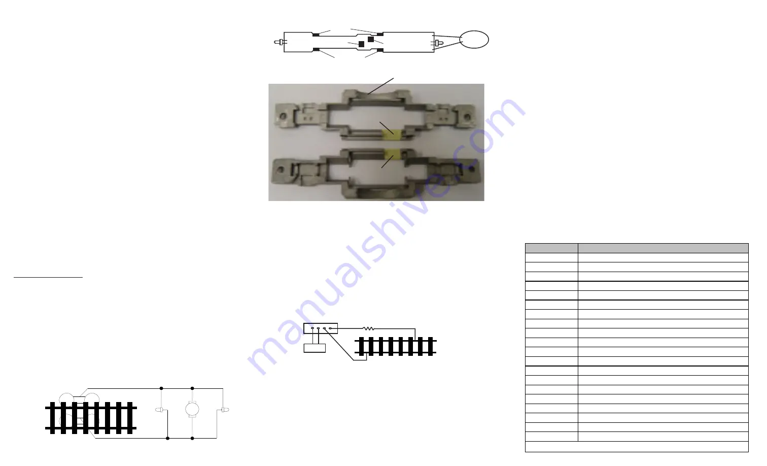
Figure 2. shows how to install 0001636 decoder
MAKING A TEST TRACK
Before you begin decoder installation, we strongly recommend building a test
track with a 27 ohm resistor to limit current. Only test your installed decoder on
the test track. The test track may prevent damage from an incorrectly installed
decoder.
Note: The program track is NOT a test track. The program track does not use a
current limiting resistor. So it can’t protect an incorrectly installed decoder.
TESTING
All MRC decoders have been factory programmed with address #3, 28/128
speed steps and maximum top voltage.
Never run the installed decoder on
your layout without first successfully running on test track.
Otherwise,
you may damage the decoder if it is not wired correctly or if you have not
properly isolated the motor and lights.
*Before installing the plastic fuel tank casting it is recommended that a
few small holes are drilled into the bottom of the casting to let the
sound out. This will give you the best fidelity and volume the decoder
has to offer.
Figure 1. Connection of standard locomotive
mill the oval shape for the speaker
Note: The “x” marks indicate
where to disconnect (isolate)
Function
Idle /M oving
Double click F0
Turns on/off accessory lighting
F1
Bell on/off
F2
Horn
F3
A ir release w hile moving or prime mover rev up during idle
F4
Coupling/air hose firing
F5
Brake release (idle) / brake squeal (moving)
F6
Dynamic brake on/off
F7
Air hose firing/uncoupling lever
F8
notch dow n (w hen CV122=3)/associated loco sound
F9
notch up (w hen CV122=3)/associated loco sound
F10
Rail w heel clack (only moving)
F11
Traction air compressor
F12
Engine cooling fan
F13*
short air release
F14*
Associated loco sound
F15*
Air pump
F16*
Associated loco sound
F17*
flange noise
F18*
Change bell type
F19*
Horn type select *
* Note: Only MRC Prodigy advance DCC has F13-F19 accessory functions
Wrap the whole notch with tape to prevent the motor’s contact from touching the
chassis. Otherwise, the decoder will be destroyed if the motor contact touches
any unwrapped part of the chassis.
wrap tape
wrap tape
Rear light
front light
motor tab
pick up
pickup tab
motor tab
PCB bottom side
13x18mm
speaker
DCC base unit
Power supply
Test track
27 ohm resistor
Figure 3. Diagram of test track
Right side pickup
Front
light
Motor
Rear
light
Left side pickup
X
X
X
X
X
X