


PAGE 34 — DCA-150SSJU — PARTS AND OPERATION MANUAL — REV. #3 (09/07/01)
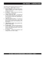
DCA-150SSJU — OUTPUT TERMINAL PANEL OVERVIEW
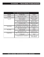
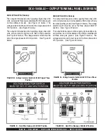
Circuit Breakers
To protect the generator from an overload, a 3-pole, 400 amp,
main
circuit breaker is provided to protect the UVW output
terminals from overload. In addition two single-pole, 20 amp
GFCI
circuit breakers are provided to protect the GFCI
receptacles from overload. Three 50 amp
load
circuit breakers
have also been provided to protect the load side of the
generator from overload. Make sure to switch
ALL
circuit
breakers to the "OFF" position prior to starting the engine.
OUTPUT TERMINAL PANEL FAMILIARIZATION
Output Terminal Panel
The “Output Terminal Panel” is provided with the following:
z
Three 240 output receptacles, 50 amp
z
Two 120V output receptacles, 20 amp
z
3 Circuit Breakers 240V @50 amps
z
2 GFCI Circuit Breakers 120V@ 20amps
Output Terminal Panel
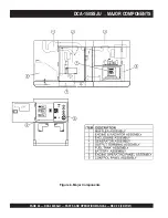
The Output Control Panel (See Figure 14) is located on the
right hand side (left from control panel) of the generator.
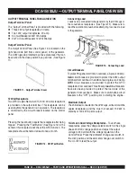
The UVW lugs are protected by a face plate cover that can
be secured in the close position by a pad lock. (See Figure
11).
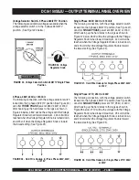
120 Volt Receptacle
Two GFCI Duplex Nema 5-20R (120V, 20 Amp) receptacle
is provided on the output terminal. This receptacle can be
used anytime the generator is in operation. The receptacle
is controlled by the circuit breaker located on the control
panel.
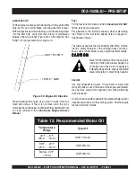
Pressing the reset button resets the receptacle after being
tripped. Pressing the "Test Button" (See Figure 12) in the
center of this receptacle will check the GFCI function. The
receptacle should be tested at least once a month.
FIGURE 12. GFCI Test Button
FIGURE 11. Output Terminal Cover
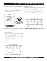
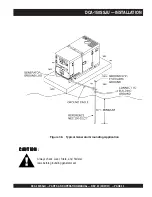
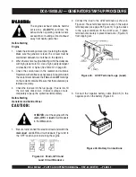
Connecting Load
Loads can be connected to the generator by the UVW Lugs or
the convenience receptacles. (See Figure 13). Make sure to
read the operation manual before attempting to connect a load
to the generator.
Maximum Output
The entire load connected to the UVW Lugs, all four slots in the
duplex receptacles, and the must not exceed 132 kW in
standby or 120 kW in prime output.
Twist Lock Dual Voltage Receptacles -
To use these
receptacles, place the voltage selector switch in the single
phase 240/120 voltage position and adjust the output
voltage to 240 volts with the voltage regulator on the
Control Panel. Place the voltmeter change-over switch to
the U-W position and the ammeter change-over switch to
the U or W to read the output.
FIGURE 13. Connecting Load
Summary of Contents for DCA-150SSJU
Page 2: ...PAGE 2 DCA 150SSJU PARTS AND OPERATION MANUAL REV 3 09 07 01 ...
Page 22: ...PAGE 22 DCA 150SSJU PARTS AND OPERATION MANUAL REV 3 09 07 01 DCA 150SSJU GENERATOR DECALS ...
Page 25: ...DCA 150SSJU PARTS AND OPERATION MANUAL REV 3 09 07 01 PAGE 25 NOTE PAGE ...
Page 99: ...DCA 150SSJU PARTS AND OPERATION MANUAL REV 3 09 07 01 PAGE 99 NOTE PAGE ...


