background image

 
Use Instructions 

Echo/Vascular User Manual (15381-C)  

Page 15 of 46 

DCR-00172 


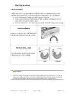
Locking the Casters 

 
The product may be equipped with total locking casters or individual locking casters.  
The total locking casters have 3 functional positions:  full swivel, steer, and full lock. 


In the neutral position all four casters may swivel and roll. 


In the steer position the front casters are held in a forward facing orientation 
and the rear casters are free to swivel. 


In the lock position all four casters are prevented from both rolling and swiveling. 


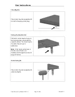
Single Pedal Braking 


Pedals are located on each side of the base 
and are used to adjust the caster function. 


Individual Locking Casters 


The locking tab is located on each caster.  
Push down to lock, lift to unlock.   


WARNING 


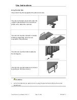
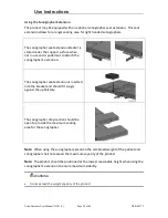
Once the product and patient have been properly positioned for the procedure, ensure the 
casters are locked and the hand controller is placed in a safe position to prevent unwanted 
contact and unwanted movement of the product surface during the procedure.   


Summary of Contents for EchoBed X

Page 1: ...Vascular User Manual 15381 C Page 1 of 46 DCR 00172 Owner s Manual EchoBed X VasScan Table X Owner _____________________ Model _____________________ Serial _____________________ Date _________________...

Page 2: ...Height 16 Adjusting Fowler 16 Adjusting Trendelenburg 16 Memory Function 17 Hand Control Lock Unlock 17 Under bed Lights 18 Using the VasScan Table X Foot Rest 19 Using the Carotid Head Rest 22 Using...

Page 3: ...allowable patient leakage current Warning Caution consult accompanying documents Any terminal which is intended for connection to an external protective conductor for protection against electric shoc...

Page 4: ...The words WARNING CAUTION and NOTE carry special meanings and should be carefully reviewed WARNING Identifies a situation that could result in injury to the patient or caregiver CAUTION Identifies a s...

Page 5: ...n equivalent receptacle marked hospital only or hospital grade If damage has occurred to the power cord immediately remove the cord from service Failure to do so could result in serious injury or deat...

Page 6: ...damage Always read manufacturer s instructions and warnings before using any cleaning product or disinfectant Refer to instructions located in this manual for vinyl cleaning recommendations Substance...

Page 7: ...s hand control The product is not intended for use in oxygen rich environments Safety Features This product is equipped with multiple automated safety features to prevent danger or damage during use...

Page 8: ...P ACTION 1 After removing padding and packaging materials locate primary power supply cord and attach to suitable grounded power outlet 2 To test actuator function locate the hand control and depress...

Page 9: ...Echo Vascular User Manual 15381 C Page 9 of 46 DCR 00172 Product Illustration Optional features may be shown...

Page 10: ...o Vascular User Manual 15381 C Page 10 of 46 DCR 00172 Controls and Indicators Unique Device Identification Label Serial Item Item Description Unique Identifier Certification Label Refer to Manual Lab...

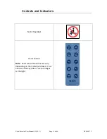
Page 11: ...ors Echo Vascular User Manual 15381 C Page 11 of 46 DCR 00172 No Sitting label Hand Control Note Hand control functions will vary depending on the model purchased Your hand control may differ from the...

Page 12: ...Controls and Indicators Echo Vascular User Manual 15381 C Page 12 of 46 DCR 00172 AC Input Battery Pedals for Single Pedal Brake Side Rail Release...

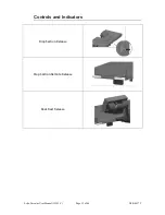
Page 13: ...Controls and Indicators Echo Vascular User Manual 15381 C Page 13 of 46 DCR 00172 Drop Section Release Drop Section Remote Release Back Rest Release...

Page 14: ...apply DC power to the product install a battery at the foot end of the product Note The battery may be charged while it is installed in the product by plugging the product into AC power WARNING To re...

Page 15: ...ation and the rear casters are free to swivel In the lock position all four casters are prevented from both rolling and swiveling Single Pedal Braking Pedals are located on each side of the base and a...

Page 16: ...inst equipment damage and injury Press and hold the applicable hand control function to adjust the seat height Adjusting Fowler The fowler section may be adjusted between 0 and 65 Press and hold the a...

Page 17: ...of the hand control will flash 3 times when the memory position has been set Setting a memory function takes approximately 3 4 seconds The memory positions can be reset to new positions by following...

Page 18: ...t is free of impediments before operating to prevent injury or equipment damage Keep hands and feet clear from beneath the patient surface when lowering surface height or making positioning adjustment...

Page 19: ...ped with a foot rest used during procedures requiring a reverse Trendelenburg position The foot rest plugs into the receiving block located on the stationary section The foot rest height can be adjust...

Page 20: ...he patient Location of Imaging Drop Section To open the drop section pull the handle to release drop section latches Or Use the remote release located on the opposite side of the support surface To cl...

Page 21: ...t positions to choose from To lower from the back rest position pull on the handle to release the back rest lock Hold the handle while lowering the drop section until it returns to its stored position...

Page 22: ...ing the head support the mounting brackets must be installed at the head end of the product The head rest mount is located underneath the head end of the fowler section Install the head rest and adjus...

Page 23: ...ace when not in use and are pulled out to attach the side rails The side rails may be oriented in multiple directions depending on the access required for the procedure The side rails must be locked i...

Page 24: ...ach the sonographer s extension The sonographer seat extension is inserted into the bracket and should fit snugly against the upholstery The sonographer drop section should be open to provide the maxi...

Page 25: ...Foley bag Storing the Hand Control The hand control may be hung on the hook located underneath the support surface The hook may be moved to the end user s preference Note If the hand control hook is...

Page 26: ...e located approximately in the locations shown Optional Battery The product may be equipped with an optional battery The battery may be charged by plugging in the product to AC power or by removing th...

Page 27: ...he following steps 1 Lower the Drop Section 2 Remove the non pinch closure flap by grasping one side of the flap and gentle separating the hook and loop fastener 3 Position the adaptor locator flanges...

Page 28: ...proper engagement of latch into receiver Adjust if necessary Operate all motors to ensure full extension retraction and correct operation The motors are permanently lubricated and require no additiona...

Page 29: ...useful life the product may be discarded in accordance with local and federal standards Recycle when possible In accordance with the European Directive 2002 96 EC on Waste Electrical and Electronic E...

Page 30: ...n caught quickly most stains such as grease blood and felt tip pens can be wiped right off Mild soap and water is the preferred method however typical hospital grade antiseptic wipes work as well For...

Page 31: ...Straight application of isopropyl alcohol Use a soft cotton cloth saturated with the cleaning material Wipe surface with damp cloth with water only after cleaning Strongest 1 1 mix of acetone and wate...

Page 32: ...6 Please have the following information ready when you call 1 Model Number or Name of Product 2 Serial Number 3 Date Received 4 Condition When Received 5 Symptom or problem Encountered Result of Troub...

Page 33: ...d and tripped internal fuse in control box Replace control box Product motion is limited at certain heights and angles Return the surface to a level position to restore full range of motion The produc...

Page 34: ...red by this manual are designed to support a 1000lb static load for emergency situations The specified maximum patient weight should be followed for normal usage EchoBed X ATTRIBUTE 201 222 223 233 Ba...

Page 35: ...Base Length 48 5 48 5 Surface Width 28 28 Surface Length 80 5 80 5 Surface Height Range To top of cushion 19 38 19 38 Trendelenburg Reverse Trendelenburg 15 30 15 30 Fowler Range 0 65 0 65 of Drop Se...

Page 36: ...117 Vinyl D O T FAR 25 853 and FMVSS302 Port of NY Boston F D Code Power Requirements ATTRIBUTE SPECIFICATION Electrical Product 100 240 VAC 50 60 Hz max 5 A Electrical Battery Charger 100 240 VAC 50...

Page 37: ...C 60601 1 2005 A1 2012 ANSI AAMI ES60601 1 2005 R 2012 and A1 2012 C1 2009 R 2012 and A2 2010 R 2012 CAN CSA C22 2 NO 60601 1 14 EN 60601 1 2006 A11 2011 A1 2013 AC 2014 IEC 60601 1 2 2007 EN ISO 1497...

Page 38: ...so comply with this standard If they do not comply electromagnetic interference between the products could cause the products to operate incorrectly If problems do occur contact the product manufactur...

Page 39: ...the user of the product should assure it is used in such an environment Emissions Test Compliance Guidance RF Emissions CISPR 11 Group 1 Group 2 The product uses RF energy only for its internal funct...

Page 40: ...hospital environment Surge IEC 61000 4 5 1 kV Differential Mode 2 kV Common Mode 1 kV Differential Mode 2 kV Common Mode Mains power quality should be that of a typical commercial or hospital environm...

Page 41: ...hs from fixed RF transmitters as determined by an electromagnetic site survey a should be less than the compliance level in each frequency range b Interference may occur in the vicinity of equipment m...

Page 42: ...ons equipment Rated maximum output power of transmitter Separation distance according to frequency of transmitter m 150 kHz to 80 MHz 80 MHz to 800 MHz 800 MHz to 2 5 GHz 0 01 0 12 0 12 0 23 0 1 0 38...

Page 43: ...RIBUTE STANDARD OPTIONAL STANDARD OPTIONAL Hand control X X Side Rails X X Single Pedal Brake Mobility X X Paper Roll Holder X X Positioning Wedge X X Sonographer Extension X X 1 Function Foot Control...

Page 44: ...rol Kit 15505 Paper Roll Holder Kit 10098 Side Rail Kit 15433 IV Pole Kit 10855 Battery Functionality 15509 Replacement Battery 15395 Wall Charger Kit 15508 VasScan Footboard 14460 Carotid Headrest Ki...

Page 45: ...dvance written permission of MPI MPI makes no other warranty either expressed or implied with respect to this product MPI specifically disclaims the implied warranties of merchantability and fitness f...

Page 46: ...nce written permission of MPI MPI makes no other warranty either expressed or implied with respect to this product MPI specifically disclaims the implied warranties of merchantability and fitness for...

Reviews: