background image


- 10 - 

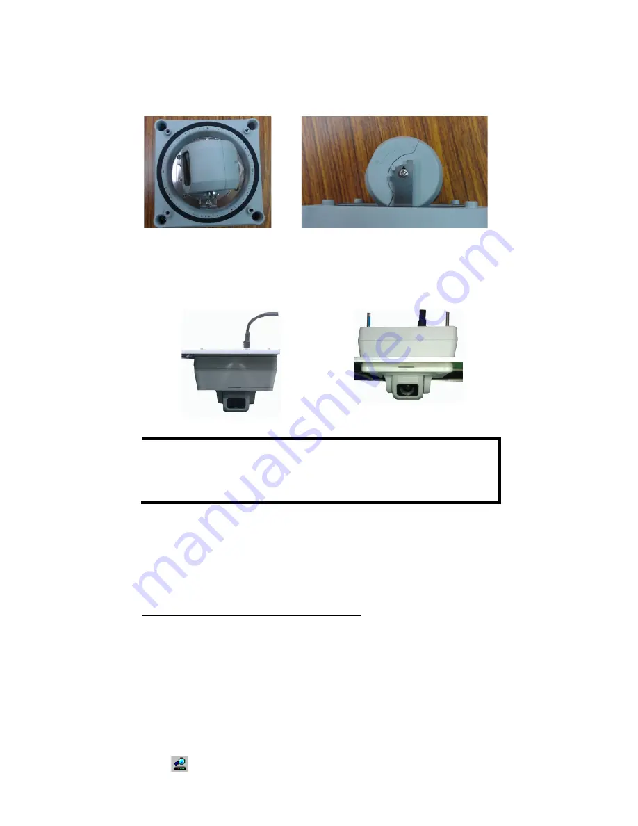
Step 4: Loosen the screws of horizontal and vertical lens position. 
Then tune the camera lens position by using the marked 
calibration or connecting to the VPort 16-M12’s web console for 
viewing the video image. After the lens position is correct, fix the 
screws. 


Step 5: Fix the top cover and then the installation is complete.


Panel Mount 

Screw the 4 top cover screws 
back. 


Flush Mount 

Screw the 4 flush mount top screws 
(in accessory) on the top cover 


NOTE 

The 4 flush mount top cover screws canfix VPort 16-M12’s top 
cover on ceilings with a maximum 5 mm of thickness. You can 
find the M4 screws by yourself, or contact Moxa for special 
support if you require longer top screws. 


Software Installation 

Step 1: Configure the VPort 16-M12’s IP address 

When the VPort 16-M12 is first powered on, the POST (Power On Self Test) 
will run for a few moments (about 30 seconds). The network environment 
determines how the IP address is assigned. 

Network Environment with DHCP Server 

For this network environment, the unit’s IP address will be assigned by 
the network’s DHCP server. Refer to the DHCP server’s IP address table to 
determine the unit’s assigned IP address. You may also use the Moxa 
VPort and Ether Device Configurator Utility (edscfgui.exe), as described 
below: 

Using the Moxa VPort and EtherDevice Configurator Utility 
(edscfgui.exe) 

1.


Run the 

edscfgui.exe

 program to search for the VPort. After the 

utility’s window opens, you may also click on the 

Search

 button 

  to initiate a search. 

Summary of Contents for VPort 16-M12 Series

Page 1: ...2011 Moxa Inc All rights reserved P N 1802000160010 Moxa IP Camera VPort 16 M12 Series Quick Installation Guide First Edition December 2011...

Page 2: ...nstalling an SD card to provide up to 32 GB of local storage The VPort 16 M12 supports both surface mounting and embedded mounting and for different viewing angles and distance requirements 5 lens typ...

Page 3: ...the camera 4 Nylock flush mount top cover screws for mounting the top cover on the ceiling Sticker for camera mounting positions Quick Installation Guide Document Software CD includes User s Manual Q...

Page 4: ...cast IGMP video streaming Support SNMP V1 V2C V3 for network system integration and management Support QoS ToS for transmission priority Built in web server for easy configuration Adjustable frame rat...

Page 5: ...cover This top cover can be removed for tuning the camera lens position Lens VPort 16 M12 provides 5 kinds of lens with different focal length 3 0mm 3 6mm 6mm 8mm and 16mm in different auxliary model...

Page 6: ...ure replacement or mass installation SD card cover To use an SD card for local storage the user can remove this SD card cover with an L type torx screw driver NOTE The VPort 16 M12 supports a standard...

Page 7: ...he VPort 16 M12 series to the network you need to use an Ethernet cable with a D code M12 connector and a M12 PoE switch or RJ45 PoE switch M12 D code to M12 D code cable M12 PoE Switch ex TN 5508 4Po...

Page 8: ...ation for tuning the lens horizontal position 0 to 360 After tuning the lens horizontal position the user can mark the position with this calibration for future replacement or mass installation 2 scre...

Page 9: ...llation sticker for drilling the holes gray color for panel mounting and green color for flush mounting Step 3 Put VPort 16 M12 on the holes Panel Mount Screw the hex nuts gaskets and washers for fixi...

Page 10: ...support if you require longer top screws Software Installation Step 1 Configure the VPort 16 M12 s IP address When the VPort 16 M12 is first powered on the POST Power On Self Test will run for a few m...

Page 11: ...o that the computer is on the same subnet as the VPort To change the IP address of the VPort manually access the VPort s web server and then navigate to the System Configuration Network General page t...

Page 12: ...installing the ActiveX Control component the homepage of the VPort 16 M12 s web based manager will appear Check the following items to make sure the system was installed properly 1 Video Images 2 Vide...

Page 13: ...ld also pay attention to the following Use separate paths to route wiring for power and devices If power wiring and device wiring paths must cross make sure the wires are perpendicular at the intersec...

Page 14: ...ctronic Shutter NTSC 1 60 to 1 120 000 sec PAL 1 50 to 1 120 000 sec S N Ratio 50 dB MIN 58 dB TYP Gamma Aperture AGC OFF AGC Control On Off Flickerless Control On Off Backlight Compensation On Off Au...

Page 15: ...CMP QoS SNMPv1 v2c v3 DDNS TFTP OPT 66 67 Ethernet 1 10 100BaseT X Ethernet port M12 D code connector Local Storage SD Socket Standard SD socket SDHC Power Requirements Input Power over Ethernet IEEE...

Page 16: ...ion Detection Includes sensitivity tuning Video Loss Video loss alarm Scheduling Daily repeat timing schedule Imaging JPEG snapshots for pre trigger post alarm images Custom Alarms HTTP event servers...

Page 17: ...cas Toll free 1 888 669 2872 Tel 1 714 528 6777 Fax 1 714 528 6778 Moxa China Shanghai office Toll free 800 820 5036 Tel 86 21 5258 9955 Fax 86 21 5258 5505 Moxa Europe Tel 49 89 3 70 03 99 0 Fax 49 8...

Reviews: