background image

- 11 - 

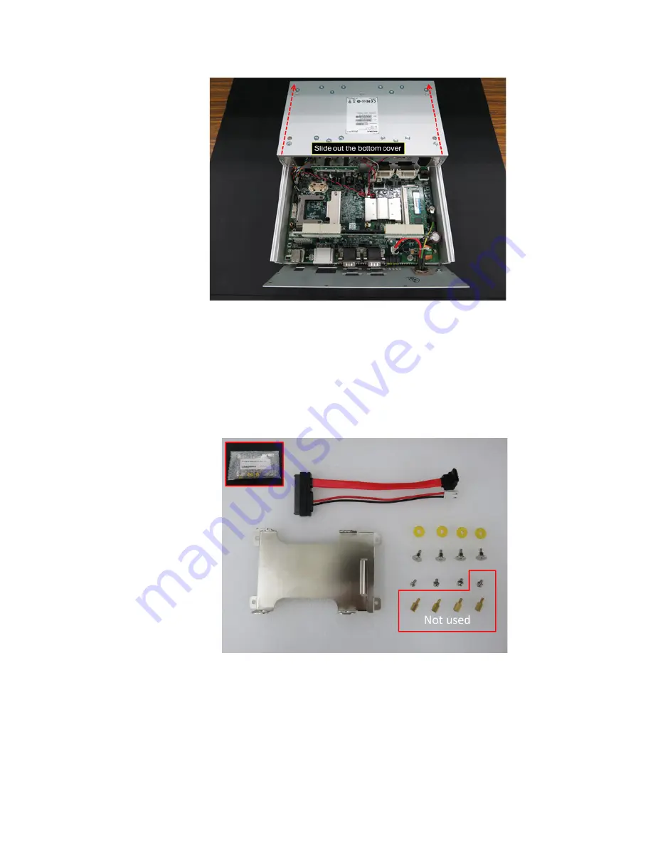
4.1.9  Slide out the bottom cover of the V2426A completely as 

shown in Figure 11. 


Figure 11 

4.2  Installing or Replacing an SSD/HDD 

4.2.1  Installing an SSD/HDD in the HDD Tray 

Follow the instructions detailed below to install an SSD/HDD in the 
HDD tray to build the SSD/HDD assembly: 
4.2.1.1  Arrange all the components from the hard disk installation 

package as shown in Figure 12. 


Figure 12 


Summary of Contents for V2426A

Page 1: ...support Moxa Americas Toll free 1 888 669 2872 Tel 1 714 528 6777 Fax 1 714 528 6778 Moxa China Shanghai office Toll free 800 820 5036 Tel 86 21 5258 9955 Fax 86 21 5258 5505 Moxa Europe Tel 49 89 3 7...

Page 2: ...nstallation Flowchart 5 4 Installing a SATA Hard Disk 5 4 1 Opening the V2426A to Access the SSD HDD Area 5 4 2 Installing or Replacing an SSD HDD 11 4 2 1 Installing an SSD HDD in the HDD Tray 11 4 2...

Page 3: ...2 Estimated installation time is 30 to 45 minutes 2 Preparing to Install an SSD HDD 2 1 Working Environment We recommend setting up a working environment with anti electro static discharge ESD equipme...

Page 4: ...02 SATA SSD HDD Refer to the V2400A Component Compatibility Guide for compatible models 2 3 2 To replace an existing SSD HDD you will require the following SATA SSD HDD Refer to the V2400A Component...

Page 5: ...access the SSD HDD installation area on the main board installing an SSD HDD assembly and reassembling the V2426A by putting back the cover and securing it with screws 4 1 Opening the V2426A to Acces...

Page 6: ...rea as shown in Figure 1 Figure 1 4 1 2 Use a Phillips screwdriver item 1 in Table 2 to loosen the four 4 screws on the front panel and then pull out two expansion slot covers Remove the two terminal...

Page 7: ...the front and rear panels as shown in Figure 3 Figure 3 4 1 4 Use a Phillips screwdriver item 1 in Table 2 to remove the twenty five 25 screws indicated with red circles on the front and rear panels...

Page 8: ...4 1 5 Press and hold the LAN1 and LAN2 connectors and partially open the front panel as shown in Figure 5 Figure 5 Keep the O rings on the LAN1 and LAN2 connectors safely and do not lose them Figure...

Page 9: ...4 1 7 Gently open the front and rear panels partially as shown in Figure 7 Refer to Figure 8 and Figure 9 to avoid pulling out any wires or cables connected to the front and rear panels Figure 7 Figur...

Page 10: ...panel vertically beside the computer on the right side without pulling out the wires as shown in Figure 10 and use a Philips screwdriver item 1 in Table 2 to remove the four 4 screws indicated with r...

Page 11: ...2 Installing or Replacing an SSD HDD 4 2 1 Installing an SSD HDD in the HDD Tray Follow the instructions detailed below to install an SSD HDD in the HDD tray to build the SSD HDD assembly 4 2 1 1 Arr...

Page 12: ...on the HDD tray as shown in Figure 13 Figure 13 4 2 1 3 Turn the SATA connector clockwise by 90 degrees and gently insert the connector head into the opening on the HDD tray until it completely passe...

Page 13: ...e with the SSD HDD and fix the SSD HDD to the tray as shown in Figure 16 Figure 16 4 2 1 5 Use a Phillips screwdriver item 1 in Table 2 to tighten the four 4 screws to secure the SSD HDD on to the tra...

Page 14: ...emoving an Existing SSD HDD 4 2 2 1 Disconnect the SATA data cable from the main board as shown in Figure 18 Figure 18 4 2 2 2 Disconnect the SATA power cable from the main board as shown in Figure 19...

Page 15: ...illips screwdriver item 1 in Table 2 to remove the four 4 screws that attach the SSD HDD assembly to the board as shown in Figure 20 Figure 20 4 2 2 4 Gently pull out the SSD HDD assembly as shown in...

Page 16: ...hillips screwdriver item 1 in Table 2 to remove the four 4 screws on the HDD tray as shown in Figure 22 Figure 22 4 2 2 6 Disconnect the SATA cable from the SSD HDD and remove the SSD HDD as shown in...

Page 17: ...le to the new SSD HDD and fix the SSD HDD to the tray as shown in Figure 24 Figure 24 4 2 2 8 Use a Phillips screwdriver item 1 in Table 2 to tighten the screws 4 nos to secure the SSD HDD to the tray...

Page 18: ...installation area on the main board do the following 4 3 1 Use a Phillips screwdriver to remove the black screw located in the SSD HDD area on the main board as shown in Figure 26 Figure 26 4 3 2 Mov...

Page 19: ...top of the four pillars in the installation area and put back cable tie as shown in Figure 28 Figure 28 4 3 4 Use a Phillips screwdriver to tighten the four 4 screws to fix the SSD HDD assembly to th...

Page 20: ...20 4 3 5 Connect the free end of the SATA power cable to the mainboard as shown in Figure 30 Figure 30 4 3 6 Connect the free end of the SATA data cable to main board as shown in Figure 31 Figure 31...

Page 21: ...ing and secure the same with screws as follows 4 4 1 Slide in the bottom cover of the V2426A from front panel towards rear panel as shown in Figure 32 Do this gently and carefully to avoid bending or...

Page 22: ...ing out the wires as shown in Figure 34 and use a Phillips screwdriver to tighten the four 4 screws marked with red circles Figure 34 4 4 4 Push the front panel back in place put back the rare panel a...

Page 23: ...cles on the front and rear panels as shown in Figure 36 Figure 36 4 4 6 Push in the expansion slot covers on the front panel and use a Philips screwdriver to tighten the four 4 screws on the expansion...

Page 24: ...re 38 5 Testing the Newly Installed SSD HDD To verify that the SSD HDD that you just installed is working fine perform the following checks 5 1 Enter the BIOS setup utility by pressing the F2 key whil...

Page 25: ...5 2 In the configuration screen select Advanced HDC Configuration as shown in Figure 40 Figure 40 5 3 Verify the information brand and model displayed for Serial ATA Port 3 as shown in Figure 41 Figur...

Page 26: ...26 5 4 Select Exit Exit Discarding Changes to exit the BIOS configuration utility Figure 42 The SSD HDD installation process is complete You can now start using the disk...

Reviews: