


- 5 -
8.
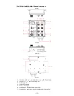
PWR1 LED: for power input 1.
9.
PWR2 LED: for power input 2.
10.
FAULT LED.
11.
MSTR/HEAD LED: for ring master or chain head.
12.
CPLR/TAIL LED: for ring coupler or chain tail.
13.
TP port’s 10/100 Mbps LED.
14.
10/100BaseT(X) port (female 4-pin shielded M12 connector with D
coding).
15.
Waterproof vent.
16.
Product label.
17.
12 Screw holes for DIN-Rail mounting kit.
18.
E2 LED: Down-side E2 Gigabit port's 1000 Mbps LED.
19.
E1 LED: Down-side E1 Gigabit port's 1000 Mbps LED.
20.
Gigabit Fiber port E1 (corresponding to port 9 in the TN-5510 User's
Manual).
21.
Gigabit Fiber port E2 (corresponding to port 10 in the TN-5510
User's Manual).
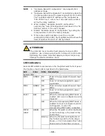
ATTENTION
Please DO NOT open or remove vent
15
. The warranty will be
invalid if the seal is removed.
All exposed connectors, including
3
,
5
,
7,
and
14
, should be
tightly covered by protective caps when they are not in use to
ensure for IP54 protection.
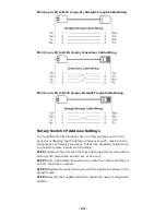
After setting rotary switch
1
, the protective cover must be fixed
properly to ensure IP54 protection.


