Moxa Technologies NPort 5200 Series Quick Installation Manual Download Page 4

- 4 - 

Hardware Installation Procedure 

STEP 1: After removing the NPort 5200 from the box, the first thing you 
should do is connect the power adapter. Connect the 12-30 VDC power 
line with the NPort 5200’s terminal block, or connect the DIN-rail power 
supply with the NPort 5200’s terminal block. 
STEP 2: Connect the NPort 5200 to a network. Use a standard 
straight-through Ethernet cable to connect to a hub or switch. When 
setting up or testing the NPort 5200, you might find it convenient to 
connect directly to your computer’s Ethernet port. In this case, use a 
cross-over Ethernet cable. 
STEP 3: Connect the NP ort 5200’s serial port to a serial device. 
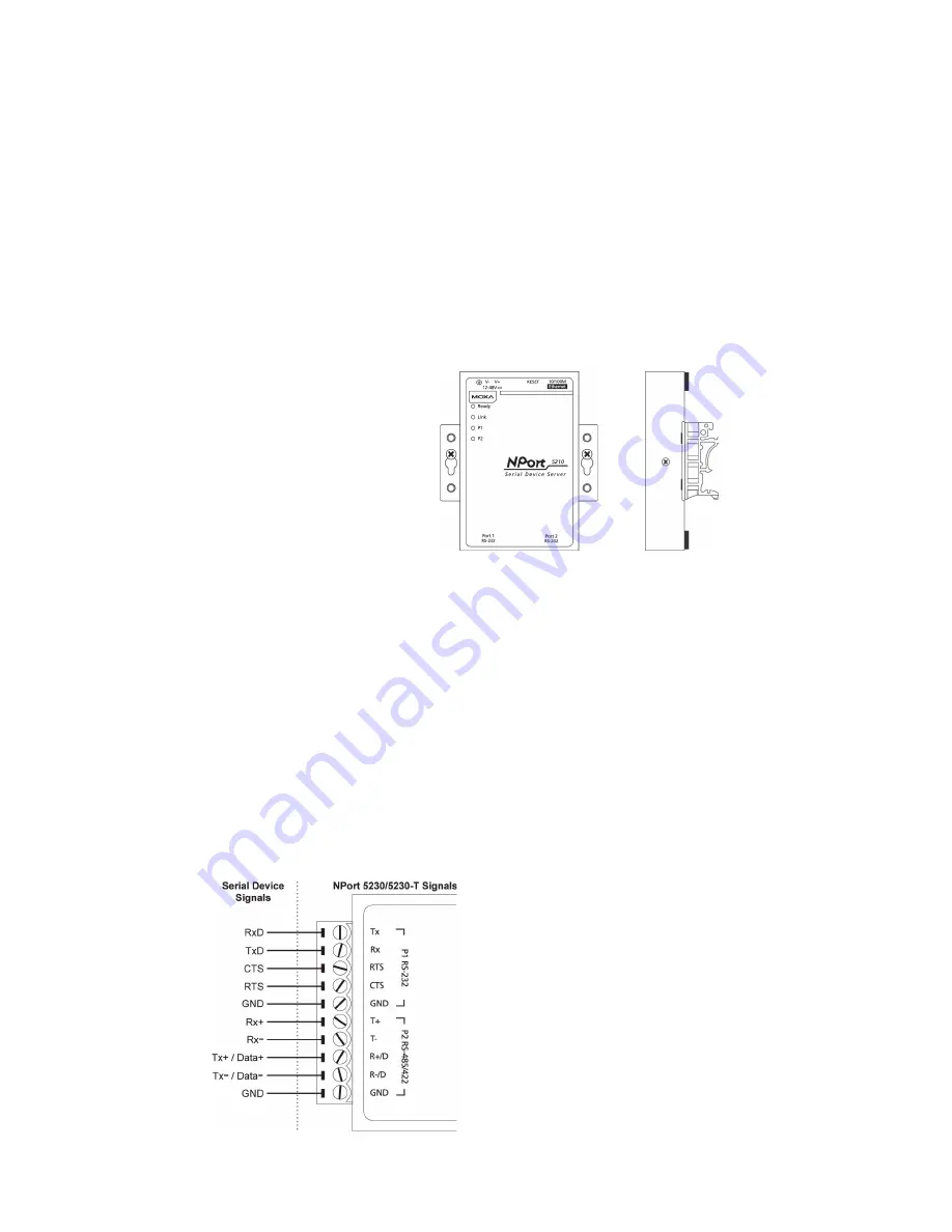
STEP 4: Placement Options 
In addition to placing the 
NPort 5200 on a desktop or 
other horizontal surface, 
you may also make use of 
the DIN-rail or wall mount 
options, as illustrated here. 

Wall Mount 


DIN-Rail 


Software Installation Information 

To install NPort Administration Suite, insert the NPort Document & 
Software CD
 into your computer’s CD-ROM drive. Once the NPort 
Installation CD
 window opens, click on the Installation button, and then 
follow the instructions on the screen. To view detailed information about 
NPort 5200 Administration Suite, click on the Documents button, 
and then select “NPort 5200 Series User’s Guide” to open the pdf version 
of this user’s guide. The PComm Lite program is also included in the 
Documentation & Software CD free of charge. Install PComm Lite to 
use the Serial Console for configuring the IP address for the first time. 

Pin Assignments and Cable Wiring— 
NPort 5230/5230-T 

Terminal Block Wiring 


Summary of Contents for NPort 5200 Series

Page 1: ...Americas Toll free 1 888 669 2872 Tel 1 714 528 6777 Fax 1 714 528 6778 Moxa China Shanghai office Toll free 800 820 5036 Tel 86 21 5258 9955 Fax 86 21 5258 5505 Moxa Europe Tel 49 89 3 70 03 99 0 Fa...

Page 2: ...150 RJ45 8 pin to DB9 M cable 150 cm CBL RJ45F9 150 RJ45 8 pin to DB9 F cable 150 cm CBL RJ45M25 150 RJ45 8 pin to DB25 M cable 150 cm CBL RJ45F25 150 RJ45 8 pin to DB25 F cable 150 cm DIN Rail Power...

Page 3: ...ction Ready Red Steady on Power is on and the NPort 5200 is booting up Blinking Indicates an IP conflict or DHCP or BOOTP server did not respond properly Green Steady on Power is on and the NPort 5200...

Page 4: ...o placing the NPort 5200 on a desktop or other horizontal surface you may also make use of the DIN rail or wall mount options as illustrated here Wall Mount DIN Rail Software Installation Information...

Page 5: ...g NPort 5210 5210 T RJ45 8 pin Connector Pinouts 8 Pin Signal 1 DSR 2 RTS 3 GND 4 TxD 5 RxD 6 DCD 7 CTS 8 DTR Cable Wiring RS 232 Four cables are available as optional accessories to connect the NPort...

Page 6: ...ort 5232I 5232I T 12 to 48 VDC 365 mA at 12V max Operating Temp Standard models 0 to 55 C 32 to 131 F T models 40 to 75 C 40 to 167 F Operating humidity 5 to 95 RH Dimensions NPort 5210 5230 5232 5210...

Page 7: ...2 ESD contact 4 kV air 8 kV EN 61000 4 3 RS 3 V m 80MHz to 1 GHz EN 61000 4 4 EFT Power 1 kV Signal 0 5 kV EN 61000 4 5 Surge AC 1 kV EN 61000 4 6 CS 3 V EN 61000 4 8 EN 61000 4 11 Safety UL 60950 1...

Reviews: