Moxa Technologies MGate 5217 Series Quick Installation Manual Download Page 4

- 4 - 

Hardware Installation Procedure 

STEP 1:

 After removing the MGate 5217 from the box, connect the MGate 

5217 to a network. Use a standard straight-through Ethernet cable to 
connect the unit to a hub or switch. When setting up or testing the MGate 
5217, you might find it convenient to connect directly to your computer’s 
Ethernet port. In this case, use a crossover Ethernet cable. 

STEP 2:

 Connect the serial port(s) of the MGate 5217 to a serial device. 

STEP 3:

 The MGate 5217 is designed to be attached to a DIN rail or 

mounted on a wall. The two sliders on the MGate 5217 rear panel serve a 
dual purpose. For wall mounting, both sliders should be extended. For 
DIN-rail mounting, start with one slider pushed in, and the other slider 
extended. After attaching the MGate 5217 on the DIN rail, push the 
extended slider in to lock the device server to the rail. The two placement 
options are illustrated in the accompanying figures. 

STEP 4: 

Connect the 12 to 48 VDC or 24 VAC power source to terminal 

block power input. 


WARNING 

This product is intended to be supplied with a UL-listed power 
adapter or DC power source marked ‘L.P.S’ or ‘Limited Power 
Source’, rated 12 to 48 VDC, 510m A (min.) or 24VAC, 50/60Hz, 
300mA (min.), and Tma 75°C (min.). 


WARNING 

The power cord adapter should be connected to a socket outlet 
with an earthing connection, or the power cord and adapter must 
comply with Class II construction. 


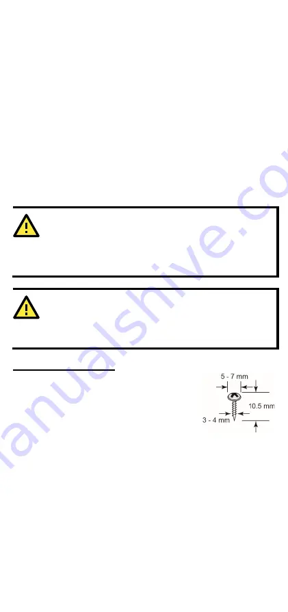
Wall or Cabinet Mounting 

Mounting the MGate 5217 Series on to a wall requires 
two screws. The heads of the screws should be 5 to 7 
mm in diameter, the shafts should be 3 to 4 mm in 
diameter, and the length of the screws should be 
more than 10.5 mm. 


Summary of Contents for MGate 5217 Series

Page 1: ...P N 1802052170011 1802052170011 MGate 5217 Series Quick Installation Guide Version 1 1 January 2021 Technical Support Contact Information www moxa com support 2021 Moxa Inc All rights reserved ...

Page 2: ...ators Name Color Function PWR1 Red Power is being supplied to the power input PWR2 Red Power is being supplied to the power input RDY Red Steady Power is on and the unit is booting up Blinking IP conflict DHCP or BOOTP server did not respond properly or a relay output occurred Green Steady Power is on and the unit is functioning normally Blinking Unit is responding to locate function Off Power is ...

Page 3: ... 3 Panel Layouts The MGate 5217 has two RJ45 Ethernet ports and two DB9 serial ports for connecting to devices ...

Page 4: ...ther slider extended After attaching the MGate 5217 on the DIN rail push the extended slider in to lock the device server to the rail The two placement options are illustrated in the accompanying figures STEP 4 Connect the 12 to 48 VDC or 24 VAC power source to terminal block power input WARNING This product is intended to be supplied with a UL listed power adapter or DC power source marked L P S ...

Page 5: ...n be adjusted by SW1 SW2 respectively DIP Switch 1 2 3 4 Pull high resistor Pull low resistor Terminator Reserve ON 1 kΩ 1 kΩ 120 Ω Reserve OFF 150 kΩ 150 kΩ Reserve Default Settings Software Installation Information You can download the User s Manual and Device Search Utility DSU from Moxa s website www moxa com Please refer to the User s Manual for additional details on using DSU The MGate 5217 ...

Page 6: ...AC DC Power Input 1 AC DC Power Input 1 Specifications Power Requirements Power Input 12 to 48 VDC and 24 VAC Power Consumption 24 VAC 300 mA max 12 to 48 VDC 510 mA max Operating Temperature 40 to 75 C 40 to 167 F Storage Temperature 40 to 85 C 40 to 185 F Operating Humidity 5 to 95 RH Magnetic Isolation Protection serial 2 kV Dimensions Without ears With ears extended 29 x 89 2 x 118 5 mm 1 14 x...

Page 7: ... 7 WARNING If the battery is replaced with the wrong type the risk of an explosion is highly likely ...

Reviews: