background image

ioPAC 5500 Hardware 

The RTUxpress Utility 


3-13 

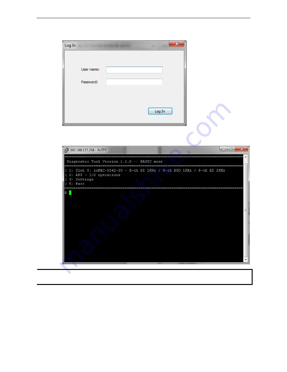
Step 2: When the Log in window appears, enter the user name and password to log in. RTUxpress will open 
PuTTY to establish an SSH connection between the ioPAC and the PC. 


Step 3: When a connection has been established, the slot and API information will be displayed in the PuTTY 
window. Use the commands listed on the screen to monitor the device. 


NOTE 

The tool may affect the operation of the ioPAC. If you want to use the tool when the ioPAC is operating, we 
strongly suggest that you to stop the ioPAC first to avoid unexpected results. 


Summary of Contents for ioPAC 5500 series

Page 1: ...ioPAC 5500 Hardware User s Manual Edition 2 0 June 2017 www moxa com product 2017 Moxa Inc All rights reserved ...

Page 2: ...s to this manual or to the products and or the programs described in this manual at any time Information provided in this manual is intended to be accurate and reliable However Moxa assumes no responsibility for its use or for any infringements on the rights of third parties that may result from its use This product might include unintentional technical or typographical errors Changes are periodic...

Page 3: ...ommunication LEDs 2 6 Cellular 2 6 User Defined LEDs LED1 and LED2 2 6 IEC 61131 3 Compliant LEDs R S and ERR 2 6 I O LEDs 2 6 The Toggle Switch 2 7 In IEC 61131 3 Models 2 7 In C C Models 2 7 Toggle Switch Factory Reset Process 2 7 Pin assignment and I O wiring guide 2 8 Pin Assignment 2 8 Digital Input 2 9 Digital Output 2 9 Analog Input Voltage 2 9 Analog Input Current 2 9 Installing a SIM card...

Page 4: ......

Page 5: ... covered in this chapter Overview Package Checklist Appearance and Dimensions Appearance Dimensions Hardware Block Diagrams ioPAC 5500 RTU Controller Block Diagram Product Hardware Specifications Product Selection Guide Product Specifications ...

Page 6: ...cUL Class 1 Division 2 certification two 10 100 Mbps Ethernet ports with two MACs Port Trunking ready and two 3 in 1 serial ports With Moxa s Active OPC Server and DA Center the ioPAC 5500 series provides a comprehensive solution for data acquisition and control applications in harsh environments Package Checklist ioPAC 5500 The ioPAC 5500 ships with the following items ioPAC 5500 controller Seria...

Page 7: ...ioPAC 5500 Hardware Introduction 1 3 Appearance and Dimensions Appearance The following figures depict ioPAC 5500 RTU controller Front View Top View ...

Page 8: ...ioPAC 5500 Hardware Introduction 1 4 Dimensions Unit mm inch Hardware Block Diagrams ioPAC 5500 RTU Controller Block Diagram CPU Board ...

Page 9: ...ioPAC 5500 Hardware Introduction 1 5 I O Board 3G Board ...

Page 10: ...ckup Memory SDRAM 64 MB Flash 32 MB SRAM 256 KB battery backup lasts for 1 week microSD Slot Up to 32 GB SD 2 0 compatible Note For units operating in extreme temperatures industrial grade wide temperature microSD cards are required Cellular for the ioPAC 5542 HSPA Series Network Quad band GSM GPRS EDGE 850 900 1800 1900 MHz Five band UMTS HSPA 800 850 AWS 1900 2100 MHz Internet HSPA Up to 5 76 Mb...

Page 11: ...er channel 120 second data buffer at 250 Hz Accuracy 0 1 FSR 25 C 0 3 FSR 40 and 75 C Sampling Rate All channels 2000 samples sec Per channel 250 samples sec Input Impedance 2M ohms min Built in Resistor for Current Input 120 ohms min Digital Input Sensor Type Wet Contact NPN or PNP Dry Contact I O Mode DI Counter or Frequency Dry Contact On short to GND Off open Wet Contact NPN DI to GND On 0 to ...

Page 12: ...SPA Series 30 to 75 C 22 to 176 F Storage Temperature 40 to 85 C 40 to 185 F Ambient Relative Humidity 5 to 95 non condensing Shock IEC 60068 2 27 Vibration IEC 60068 2 6 Altitude Up to 2000 m Note Please contact Moxa if you require products guaranteed to function properly at higher altitudes Standards and Certifications Safety UL 508 EMC EN 55022 24 EMI FCC Part 15 Subpart B Class A CISPR 22 EMS ...

Page 13: ...ED Indicators System LEDs Communication LEDs Cellular User Defined LEDs LED1 and LED2 IEC 61131 3 Compliant LEDs R S and ERR I O LEDs The Toggle Switch In IEC 61131 3 Models In C C Models Toggle Switch Factory Reset Process Pin assignment and I O wiring guide Pin Assignment Digital Input Digital Output Analog Input Voltage Analog Input Current Installing a SIM card Connecting to the Network Ethern...

Page 14: ...n you take it out of the box To install the ioPAC 5500 on a DIN Rail follow below steps NOTE A wall mount kit can be purchased separately STEP 1 Insert the top of the DIN rail into the slot just below the stiff metal spring STEP 2 The DIN rail attachment unit will snap into place as shown to the right Removing the ioPAC 5500 from a DIN Rail To remove the ioLogik unit from the DIN rail simply rever...

Page 15: ...seconds for the operating system to boot up The green Ready LED will not turn on until the operating system is ready ATTENTION This product is intended to be supplied by a Listed Power Unit with output marked LPS and rated for 9 48 VDC minimum requirements For railway rolling stock applications these devices must be supplied by a galvanic isolated power supply with design based on the EN 50155 sta...

Page 16: ...remove the card cover to install your microSD card When inserting a microSD card remember to keep the front edge of the card facing down Follow these steps to remove or install a microSD card 1 Remove the screw holding the card cover in place 2 a Insert a microSD card into the microSD card slot or b Remove the microSD card from the microSD card slot 3 Fasten back the screw holding the card cover i...

Page 17: ...K ERR Error Red System I O services error OFF No error auto update if error fixes Communication LAN1 LAN2 Ethernet Connection Green 100Mb Amber 10Mb Blinking data transmitting Off disconnected P1 P2 Serial Connection Green Transmitting data Tx Amber Receiving data Rx Off disconnected Link Cellular Connection Green ISP IP retrieved Off ISP disconnected Cellular Signal 1 2 3 ON RSSI 24 1 2 ON 18 RSS...

Page 18: ... LED is off the serial connection is disconnected LAN1 and LAN2 The ioPAC controller comes with two Ethernet ports with the LAN1 and LAN2 LEDs used to represent the status of the two connections When the LED is green data is transmitting at 100 Mbps When the LED is amber data is transmitting at 10 Mbps When the LED is blinking data is being transmitted When the LED is off there is no Ethernet conn...

Page 19: ...oggle Switch Factory Reset Process Use the following procedure to reset the ioPAC to the factory defaults Note that when you reset the ioPAC all of your tag definitions software programs and files will be deleted and the service and runtime engine will be restarted 1 When the system is booting up and the RDY LED is blinking GREEN hold the toggle switch in the reset position 2 Continue to hold togg...

Page 20: ... DIO7 15 DIO0 Digital Input Output Channel 0 16 DIO1 Digital Input Output Channel 1 17 DIO2 Digital Input Output Channel 2 18 DIO3 Digital Input Output Channel 3 19 DIO4 Digital Input Output Channel 4 20 DIO5 Digital Input Output Channel 5 21 DIO6 Digital Input Output Channel 6 22 DIO7 Digital Input Output Channel 7 23 GND Ground 24 GND Ground 25 AI0 Analog Input Channel 0 26 AI1 Analog Input Chan...

Page 21: ...ioPAC 5500 Hardware Installation 2 9 Digital Input Digital Output Analog Input Voltage Analog Input Current ...

Page 22: ...performed on the controller Lan Port 1 Lan Port 2 Parameter Supported Values Parameter Supported Values IP Address Default 192 168 127 254 IP Address Default 192 168 126 254 Subnet Mask Default 255 255 255 0 Subnet Mask Default 255 255 255 0 Gateway Default 0 0 0 0 Gateway Default 0 0 0 0 IP Address is the IP address of the controller Subnet Mask determines the subnet on which the controller is lo...

Page 23: ...thernet redundancy In the following diagram both LAN ports on each ioPAC RTU controller are connected to a managed switch on an Ethernet network running SCADA software For more details regarding configuration setup refer to the ioPAC RTU Software User s Manual Serial Connectivity Connecting to a Serial Device The ioPAC RTU is equipped with two 3 in 1 serial ports that support RS 232 422 485 making...

Page 24: ...he following diagram shows the 4 pin serial connector and pin connections Pin Assignment for the Serial Console Port Pin Definition 1 TxD 2 RxD 3 NC 4 GND Serial Console Default Settings Parameter Value Baudrate 115200 bps Parity None Data bits 8 Stop bits 1 Flow Control None Terminal VT100 We recommend using Moxa PComm Terminal Emulator to connect to the serial console The following steps describ...

Page 25: ...al screen Battery The ioPAC RTU controller is equipped with one built in rechargeable VL2020 3V battery for the SRAM and one 3V rechargeable battery model number VL 1220 for the Real Time Clock RTC Rechargeable battery VL2020 for SRAM Sustains at least 1 week without power supply Capacity 20 mAh Typical consumption 25 C 4 μA 5 year warranty Rechargeable battery VL 1220 for RTC Sustains power for a...

Page 26: ...ioPAC 5500 Hardware Installation 2 14 Caution Do NOT attempt to replace the battery Contact your local dealer for replacement assistance ...

Page 27: ...anaged and configured over an Ethernet using RTUxpress which provides easy access to all status information and ready to run service settings The following topics are covered in this chapter RTUxpress Introduction Quick Start User Interface Device and Service Configuration Settings Page Log Message Window ...

Page 28: ... value of a pre defined internal variable to trigger a logging service From the point of view of the engineer responsible for programming the focus has changed from incorporating lots of APIs to just configuring simple tags instead This change of focus greatly reduces the programming effort Moxa s ioPAC programmable controllers provide ready to run services including alarms data logging and commun...

Page 29: ...uick Start window to appear the next time you log in select the Do not show this Quick Start again checkbox before proceeding New Project When you create a new ioPAC 8600 project for ioPAC 8600 device configuration you can specify the Project Name set the Product Series to ioPAC 8600 and choose the C C or IEC 61131 3 programming language from the Select Device dropdown box Click OK to proceed ...

Page 30: ...ect the model of power module you are using from the Power 1 Module dropdown box ioPAC 8600 9 slot and 12 slot backplane modules support redundant power modules If you are using either a 9 slot or 12 slog module you can select an additional power module from the Power 2 Module dropdown box NOTE You must specify the same power module models in the Power 1 Module and Power 2 Module dropdown boxes Op...

Page 31: ... 5500 Hardware The RTUxpress Utility 3 5 Help Click the Help button to open the RTUxpress help utility and then select a help topic from the left menu Exit Click the Exit icon to close the RTUxpress utility ...

Page 32: ...erface The RTUxpress interface is divided into six main areas Menu bar Tool bar Device configuration options Service configuration options Settings panel Log message panel Log Message Window Device and Service Configuration Settings Page Tool Bar Menu Bar ...

Page 33: ...project Export Configuration to ioPAC Export the configuration file to an ioPAC Programmable Controller Import Configuration from ioPAC Import the configuration file from an ioPAC Programmable Controller Export Tag Name to C Header File Export the tag name to a C header file for use in a C C program Exit Close the RTUxpress utility Tools The following options are available under the Tools menu ite...

Page 34: ...e settings for the RTUxpress project Device Information Get the device information for a particular device NOTE A username and password are required to retrieve device information the default Username Password is moxa moxa for the ioPAC 8600 CPU30 series and root root for other ioPAC series products ...

Page 35: ...ioPAC 5500 Hardware The RTUxpress Utility 3 9 Time Sync Synchronize the device time with the PC s time or set the time manually Modify Password Modify the administrator password ...

Page 36: ...ioPAC 5500 Hardware The RTUxpress Utility 3 10 Reboot Device Reboot the ioPAC Programmable Controller ...

Page 37: ...Reset all settings and configurations to default settings IEC 61131 3 Setting a Resource information Indicates how many resources are supported by the ioPAC and whether or not the resources are running b ISaGRAF Runtime Engine Reset to Default Deletes all resources and programs in the ioPAC and restarts the ISaGRAF runtime engine ...

Page 38: ...ormance However we recommend enabling it so that runtime details will be logged when the ioPAC experiences unexpected errors Diagnostic Testing Tool The tool can be used to pre test or monitor the IO status of the device Take the following steps to use the tool Step 1 Start the tool key in an IP address or auto search for a device and then then click submit ...

Page 39: ...tween the ioPAC and the PC Step 3 When a connection has been established the slot and API information will be displayed in the PuTTY window Use the commands listed on the screen to monitor the device NOTE The tool may affect the operation of the ioPAC If you want to use the tool when the ioPAC is operating we strongly suggest that you to stop the ioPAC first to avoid unexpected results ...

Page 40: ...nfigure the preferences shown below Network Interface Allows you to select the network interface Help View Help Opens the RTUxpress chm help utility Moxa ioPAC ISaGRAF Reference Manuals Opens the Moxa_ioPAC_ISaGRAF chm utility About RTUxpress it will show the RTUxpress utility version ...

Page 41: ...roject Add Module Add an ioPAC I O module Delete Module Delete an ioPAC I O module Device Information Get device information Time Sync Device time synchronization Export Configuration to ioPAC Export a configuration file to the ioPAC Programmable controller Import Configuration from ioPAC Imports the configuration file from ioPAC Programmable Controller Help Opens the RTUxpress chm help utility ...

Page 42: ... been added to the device ioPAC also provides services Modbus SNMP Data Logging etc to reduce the developer s effort Configure the function in the service configuration page and then upload the configuration to the device The service will start working automatically Device Configuration Service Configuraion Settings Page Detailed device and configuration settings will be displayed in this window C...

Reviews: