background image

A


A.


Liquid Crystal Display Module (LCM) 

The ioLogik R2140 supports an optional detachable liquid crystal display module (LCM) for easier field 
maintenance. The LCM is hot-pluggable and can be used to configure the network settings or display other 
settings. When plugged in, the module displays the ioLogik R2140 “home page,” and pressing any button takes 
you into the settings and configuration. 

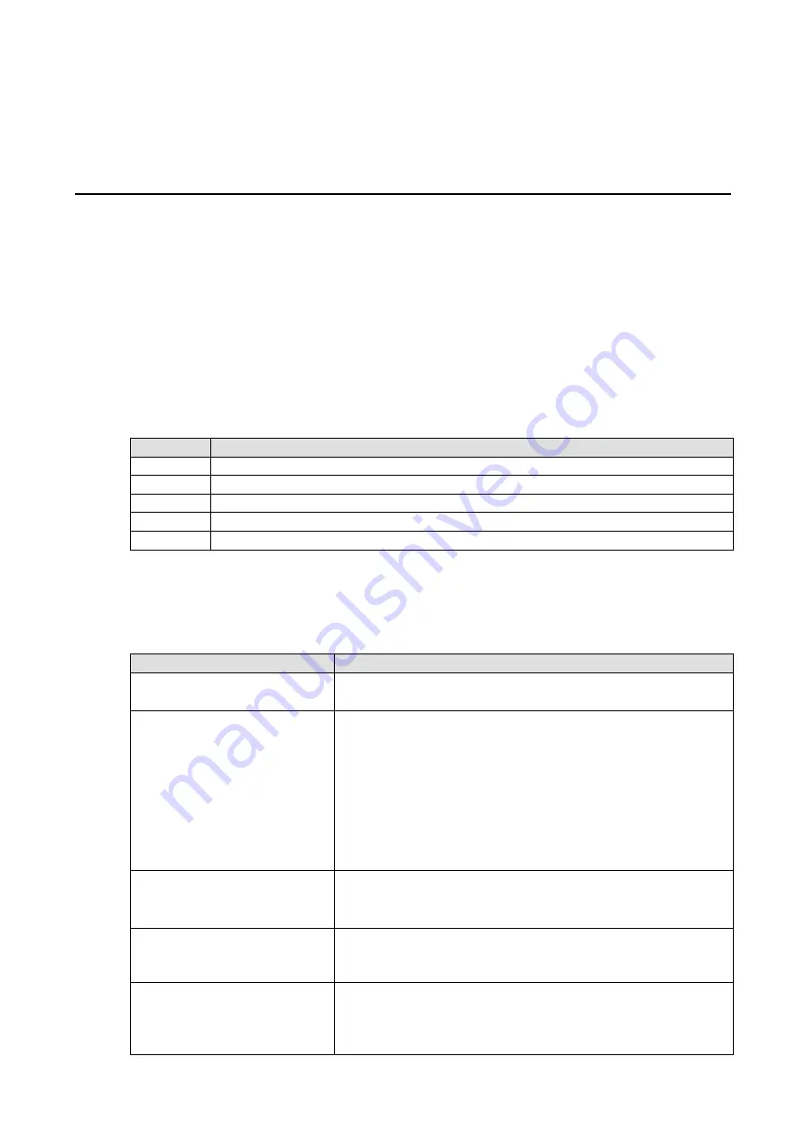
LCM Controls 

The up and down buttons navigate between the current options. The right and left buttons enter and exit the 
submenus. The center button is used when modifying settings or restarting the server. 

Button 

Function 

Up 

go to the previous item 

Down 

go to the next item 

Left 

exit the current submenu and return to the previous menu (go up one level) 

Right 

enter the selected submenu (go down one level) 

Center 

enter/exit editing mode 

An “e” in the upper right hand corner of the display indicates that the parameter can be modified. Press the 
center button on the LCM to modify that parameter’s settings. 

LCM Options 

Display 

Explanation / Actions 

ioLogik R2140 

ID:01 Bps:115200 

This is the default “home page” showing the IP address. Press the down 
button to view the submenus. 

<ioLogik R2140> 

server 

Enter this submenu to display information about the specific server you 
are viewing: 


serial number 


name 


location 


R2140 f/w ver 


display module f/w ver 


model name 

<ioLogik R2140> 

serial port 

Enter this submenu to display the RS-485 serial communication port 
settings: 


RS-485 Setting: 115200,n,8,1 

<ioLogik R2140> 

i/o setting 

Enter this submenu to access I/O channel status. Press up or down to 
navigate through the different I/O channels without having to go back to 
the previous menu. 

<ioLogik R2140> 

save/restart 

Enter this submenu to display the restart now submenu. Enter the 
restart now submenu to display the restart option. Press the center 
button to modify this option, then select enable to save changes and 
reboot the I/O server. The disable option has no effect. 

Summary of Contents for ioLogik R2140

Page 1: ...ioLogik R2140 User s Manual Edition 7 1 January 2017 www moxa com product 2017 Moxa Inc All rights reserved...

Page 2: ...this manual or to the products and or the programs described in this manual at any time Information provided in this manual is intended to be accurate and reliable However Moxa assumes no responsibil...

Page 3: ...in Screen Overview 3 5 Wiring Guide 3 6 Menu Items 3 7 File 3 7 System 3 7 Sort 3 8 Help 3 8 Quick Links 3 8 Main Window 3 9 I O Configuration Tab General 3 9 Server Info Tab 3 9 Server Settings Tab G...

Page 4: ...Bus D 1 TB1 and TB2 Power Input RS 485 Connector D 1 TB3 Analog Input and Output Terminal D 2 Analog Output D 2 Schematic D 2 Connection D 2 Analog Input D 3 Voltage Mode Schematic D 3 Current Mode Sc...

Page 5: ...nnection The following topics are covered in this chapter Overview Optional Liquid Crystal Display Module LCM Product Features Package Checklist Specifications Physical Dimensions Without LCM With Opt...

Page 6: ...ng and works with any ioLogik E or R series product Product Features 8 analog input AI channels mV V mA with wire off detection at 4 to 20 mA 2 analog output AO channels for voltage or current actuato...

Page 7: ...el enabled 0 75 samples sec Built in Resistor for Current Input 106 ohms Input Impedance 900 k Analog Output Resolution 12 bits Output Range 0 to 10 V 4 to 20 mA Drive Voltage 15 VDC for current outpu...

Page 8: ...4 6 EN 61000 4 8 EN 61000 4 11 EN 61000 6 2 Shock IEC 60068 2 27 Freefall IEC 60068 2 32 Vibration IEC 60068 2 6 Green Product RoHS CRoHS WEEE Note Please check Moxa s website for the most up to date...

Page 9: ...ioLogik R2140 Introduction 1 5 With Optional LCM all units in mm...

Page 10: ...DY LED will turn red as you are holding the reset button down The factory defaults will be loaded once the RDY LED turns green again You may then release the reset button Pin Assignments System Bus Pi...

Page 11: ...N5 VIN5 VIN6 VIN6 VIN7 VIN7 VOUT0 VOUT0 Pin 19 20 21 22 23 24 Signal IOUT 0 IOUT 0 VOUT1 VOUT1 IOUT 1 IOUT 1 LED Indicators System LEDs PWR red Power is on off Power is off RDY red System error green...

Page 12: ...ik R2140 The following topics are covered in this chapter Hardware Installation Connecting the Power Grounding the ioLogik R2140 Connecting to Analog Sensors and Devices Setting the RS 485 Baudrate Se...

Page 13: ...n shut off power to the sensors first then the ioLogik Do not exceed the maximum current for the wiring Determine the maximum possible current for each power wire and common wire Observe all electrica...

Page 14: ...l setting and corresponding baudrate 0 115200 1 57600 2 38400 3 19200 4 9600 5 4800 6 2400 7 1200 Setting the RS 485 Unit ID The ioLogik R2140 needs to be assigned a unit ID in order to use the RS 485...

Page 15: ...MXIO DLL library or ioEventLog separately 2 Open ioAdmin After installation is finished run ioAdmin from Start Program Files MOXA IO Server Utility ioAdmin 3 Search for the server On the menu bar sele...

Page 16: ...on to ioAdmin Features of ioAdmin Searching for the Unit ioAdmin Main Screen Main Screen Overview Wiring Guide Menu Items File System Sort Help Quick Links Main Window I O Configuration Tab General Se...

Page 17: ...ists of following software ioAdmin ioLogik 2000 Wiring Guide ioLogik 4000 Wiring Guide Features of ioAdmin Remote Management Over the RS 485 network ioAdmin allows users to find and configure multiple...

Page 18: ...lowing information file name date and time model information Modbus addresses Server Management List ioAdmin can import and export a list of ioLogik servers that are being managed This file can make i...

Page 19: ...ION If ioAdmin is unable to find your ioLogik R2140 make sure that the baudrates match Please refer to Chapter 2 for setting or viewing the baudrate ATTENTION Even if ioAdmin is unable to find your io...

Page 20: ...k R2140 and the status of every I O channel below it The other tabs in the main window take you to server and network settings and further functions are available when you log on as an administrator N...

Page 21: ...e wiring guide by right clicking the graphic of the ioLogik R2140 in the I O Configuration tab Select Wiring Guide in the submenu to open a help file showing the wiring information and electrical char...

Page 22: ...ik servers on the network When connecting for the first time or recovering from a network disconnection you can use this command to find I O servers that are on the network Network Interface allows yo...

Page 23: ...apter IP is used to re assign an IP address to the NA 4010 network adapter for ioLogik 4000 systems Sort The Sort menu allows the server list in the navigation panel to be sorted by connection type an...

Page 24: ...the status of every I O channel This is the default tab when you first open ioAdmin Server Info Tab The Server Information tab provides the Modbus addresses for system configuration items This helps...

Page 25: ...enever you start up ioAdmin or boot up restart the ioLogik R2140 When you install the ioLogik R2140 for the first time the password will be blank and you may simply click Login Additional tabs and fun...

Page 26: ...O analog output channels that can be set individually to 0 to 10V 4 to 20 mA Power On Settings Use this field to set the initial status for the AO channel when the ioLogik is powered on Safe Status Se...

Page 27: ...Administrator You may set up a password server name location date time zone and time server in the Server Settings tab Firmware Update Tab The ioLogik R2140 supports remote firmware updates through t...

Page 28: ...ach channel s response to a lost network connection When the ioLogik R2140 loses its network connection as specified in the timeout the Host Connection Watchdog will switch the ioLogik R2140 to Safe S...

Page 29: ...ver by using its Unit ID This function is used when cascading multiple I O servers over RS 485 Restart System Select this command to restart the ioLogik from a remote site You will need to log in as a...

Page 30: ...d a configuration that was exported to a text file You will need to restart the ioLogik in order for the new configuration to take effect This command may be used to restore a configuration after load...

Page 31: ...This chapter explains how to use the ioLogik R2 140 as an extension module to ioLogik E2000 I O servers The following topics are covered in this chapter Introductino Cascading System Bus Hardware Inst...

Page 32: ...in assignments for the female system bus connector are shown below This is the connector that protrudes from the right side of the unit Pin 1 2 3 4 5 Signal V V V V NC Pin 6 7 8 9 10 Signal NC Data SY...

Page 33: ...ns the ioLogik E2210 and R2140 are used as examples 1 Verify that the E2210 has been installed and has been opened in ioAdmin Snap the E2210 and R2140 together Set the unit ID for the R2140 starting f...

Page 34: ...d R2140 as examples 1 Verify that the E2210 has been installed and has been opened in ioAdmin Snap the R2110 onto the E2210 then snap the R2140 onto the R2110 Set the unit IDs for the R2110 and R2140...

Page 35: ...ect Delete I O Server in the context menu Limitations There are some limitations when using the ioLogik R2140 as an extension module to ioLogik E2000 servers Although each I O channel on a cascaded mo...

Page 36: ...play indicates that the parameter can be modified Press the center button on the LCM to modify that parameter s settings LCM Options Display Explanation Actions ioLogik R2140 ID 01 Bps 115200 This is...

Page 37: ...ioLogik R2140 Liquid Crystal Display Module LCM A 2 ATTENTION Any configuration changes that are made through the LCM will not take effect until the ioLogik R2140 is restarted...

Page 38: ...rite 1 reset AI min value 0 return illegal data value 00003 0x0002 1bit Reset CH2 AI min value Read 0 no action Write 1 reset AI min value 0 return illegal data value 00004 0x0003 1bit Reset CH3 AI mi...

Page 39: ...e 0 return illegal data value 00010 0x0009 1bit Reset CH1 AI max value Read 0 no action Write 1 reset AI max value 0 return illegal data value 00011 0x000A 1bit Reset CH2 AI max value Read 0 no action...

Page 40: ...06 0x0005 1 word CH5 read AI value 30007 0x0006 1 word CH6 read AI value 30008 0x0007 1 word CH7 read AI value 30009 0x0008 1 word CH0 read AI min value 30010 0x0009 1 word CH1 read AI min value 30011...

Page 41: ...e 40008 0x0007 1 word CH1 AO range 0 0 10 VDC 1 4 20 mA Other return illegal data value 40009 0x0008 1 word CH0 AO power on range 0 0 10 VDC 1 4 20 mA Other return illegal data value 40010 0x0009 1 wo...

Page 42: ...rn illegal data value 40017 0x001 0 1 word CH4 AI range 00 150 mV 01 500 mV 02 5V 03 10V 04 0 20 mA 05 4 20 mA Other return illegal data value 40018 0x001 1 1 word CH5 AI range 00 150 mV 01 500 mV 02...

Page 43: ...gal data value 40023 0x0016 1 word CH2 AI power on range 00 150 mV 01 500 mV 02 5V 03 10V 04 0 20 mA 05 4 20 mA Other return illegal data value 40024 0x0017 1 word CH3 AI power on range 00 150 mV 01 5...

Page 44: ...rn illegal data value 40029 0x001C 1 word CH0 AI safe range 00 150 mV 01 500 mV 02 5V 03 10V 04 0 20 mA 05 4 20 mA Other return illegal data value 40030 0x001D 1 word CH1 AI safe range 00 150 mV 01 50...

Page 45: ...0V 04 0 20 mA 05 4 20 mA Other return illegal data value 40035 0x0022 1 word CH6 AI safe range 00 150 mV 01 500 mV 02 5V 03 10V 04 0 20 mA 05 4 20 mA Other return illegal data value 40036 0x0023 1 wor...

Page 46: ...ured with the following factory defaults RS 485 Unit ID 1 Baudrate 115200 Kbps Communication Watchdog Disable AI Input Range 10 to 10V AO Output Range 0 to 10V AO Safe Status Off 0V Power On Status Of...

Page 47: ...ents System Bus Pin 1 2 3 4 5 Signal V V V V NC Pin 6 7 8 9 10 Signal NC Data SYNC Data GND TB1 and TB2 Power Input RS 485 Connector TB1 Power Input TB2 RS 485 Pin 1 2 3 4 5 6 Signal V V FG D D SG NOT...

Page 48: ...Terminal Pin 1 2 3 4 5 6 7 8 9 Signal VIN0 VIN0 VIN1 VIN1 VIN2 VIN2 VIN3 VIN3 VIN4 Pin 10 11 12 13 14 15 16 17 18 Signal VIN4 VIN5 VIN5 VIN6 VIN6 VIN7 VIN7 VOUT0 VOUT0 Pin 19 20 21 22 23 24 Signal IOU...

Page 49: ...ioLogik R2140 Pinouts and Cable Wiring D 3 Analog Input Voltage Mode Schematic Current Mode Schematic Connection...

Reviews: