background image

ioLogik R1200 Series 

Using ioSearch 


3-11 

Configuring Digital Output Channels 


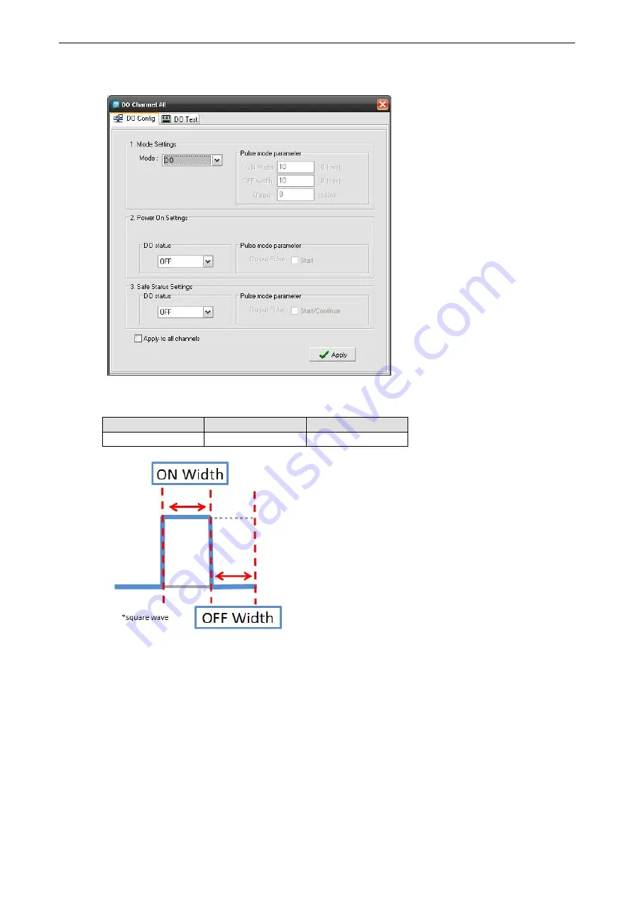
Each ioLogik R1200 digital output channel can be set to “DO” or “Pulse Output” mode. In DO mode, the 
specifications are as follows. 

Type 

Logic 0 (OFF) 

Logic 1 (ON) 

DO mode 

Open 

Short 


In “Pulse Output” mode, the selected digital output channel will generate a square wave as specified in the 
pulse mode parameters. The Low and High parameters are in multiples of 0.1 ms, with a maximum setting of 
65535. To set the low level width for 5 ms, you would enter 50 (because 50 

× 

0.1 ms = 5 ms). A setting of 100 

for both Low and High would generate a square wave with a 20 ms cycle. The Output parameter specifies the 
number of pulses to send. When set to 0, the system will send pulses continuously. 

Summary of Contents for ioLogik R1200 Series

Page 1: ...ioLogik R1200 Series User s Manual Edition 2 1 January 2016 www moxa com product 2016 Moxa Inc All rights reserved ...

Page 2: ...es to this manual or to the products and or the programs described in this manual at any time Information provided in this manual is intended to be accurate and reliable However Moxa assumes no responsibility for its use or for any infringements on the rights of third parties that may result from its use This product might include unintentional technical or typographical errors Changes are periodi...

Page 3: ...Dual RS 485 or Repeater Settings 2 5 Jumper Settings DIO and AI 2 6 Pull High Low DIP Switch Settings for the RS 485 Port 2 6 Software Installation 2 7 ioSearch Installation 2 7 Initial Setup by USB 2 9 Restore Factory Default Settings 2 10 3 Using ioSearch 3 1 Introduction to ioSearch 3 2 ioSearch Main Screen 3 2 Main Screen Overview 3 2 ioSearch Setup 3 3 System 3 3 Sort 3 5 Help 3 6 Quick Links...

Page 4: ...isters Functions 3 6 16 A 10 R1214 Modbus Mapping A 12 0xxxx Read Write Coils Functions 1 5 15 A 12 1xxxx Read Only Coils Function 2 A 14 3xxxx Read Only Registers Function 4 A 14 4xxxx Read Write Registers Functions 3 6 16 A 14 R1240 Modbus Mapping A 15 0xxxx Read Write Coils Functions 1 5 15 A 15 3xxxx Read Only Registers Function 4 A 16 4xxxx Read Write Registers Functions 3 6 16 A 17 R1241 Mod...

Page 5: ...oduct Model Information Ordering Information Specifications Common Specifications ioLogik R1210 ioLogik R1212 ioLogik R1214 ioLogik R1240 ioLogik R1241 Physical Dimensions Hardware Reference Panel Guide LED Indicators Switch Settings DI Circuit Diagram DIO Circuit Diagram Relay Circuit Diagram AI Circuit Diagram ...

Page 6: ...rcuits Multi functional I O support for DI event counter DO and pulse output Modbus RTU support for control by SCADA software including Wonderware InTouch and GE Intellution iFix32 Monitoring and configuration via ioSearch Windows utility Hardware detection over RS 485 via ioSearch Package Checklist The ioLogik R1200 is shipped with the following items 1 ioLogik R1200 remote I O product Document a...

Page 7: ...s RTU Physical Characteristics Wiring I O cable max 16 AWG Dimensions 27 8 x 124 x 84 mm 1 09 x 4 88 x 3 31 in Environmental Limits Operating Temperature Standard Models 10 to 75 C 14 to 167 F Wide Temp Models 40 to 85 C 40 to 185 F Storage Temperature 40 to 85 C 40 to 185 F Ambient Relative Humidity 5 to 95 non condensing Standards and Certifications Safety UL 508 EMI EN 55022 EN 61000 3 2 EN 610...

Page 8: ...ts and Outputs Digital Inputs 8 channels Configurable DIOs 8 channels Isolation 3K VDC or 2K Vrms Digital Input Sensor Type Wet Contact NPN or PNP Dry Contact I O Mode DI or Event Counter Dry Contact On short to GND Off open Wet Contact DI to COM On 10 to 30 VDC Off 0 to 3 VDC Common Type 8 points per COM Counter Frequency 2 5 kHz power off storage Digital Filtering Time Interval Software selectab...

Page 9: ...elay Output Type Form A N O power relay Contact Current Rating Resistive Load 5 A 30 VDC 250 VAC 110 VAC Breakdown Voltage 500 VAC Relay On Off Time 1500 ms Max Initial Insulation Resistance 1000 M ohms min 500 VDC Mechanical Endurance 5 000 000 operations Electrical Endurance 100 000 operations 5 A resistive load Contact Resistance 100 m ohms max Pulse Output 0 3 Hz at rated load Note Ambient hum...

Page 10: ... 12 Hz Input Impedance 10M ohms min Built in Resistor for Current Input 120 ohms Power Requirements Power Input 24 VDC nominal 12 to 48 VDC Power Consumption 216 mA 24VDC ioLogik R1241 Inputs and Outputs Analog Outputs 4 channels Isolation 3K VDC or 2K Vrms Analog Output Resolution 12 bits Output Range 0 to 10 VDC 4 to 20 mA Voltage Output 10 mA max Accuracy 0 1 FSR 25 C 0 3 FSR 40 and 75 C Load R...

Page 11: ...or for the two RS 485 ports is a 5 pin 3 81 terminal block 2 RS 485 ports with 1 ground pin The power connector is on the top and the reset button is on the bottom of the product There are also two dials for Board ID setup and a 2 pin DIP switch for Initial Run mode and Dual RS 485 Repeater mode setup Hardware Reference Panel Guide ...

Page 12: ...dy Flashing Flashes every 1 sec when the Locate function is triggered Flashing Flashes every 0 5 sec when the firmware is being upgraded Flashing Flashing USB upgrade is triggered OFF System is not ready Port 1 P1 Green Serial connection enabled Flashing Transmitting or receiving data Port 2 P2 Green Serial connection enabled Flashing Transmitting or receiving data Switch Settings The R1200 series...

Page 13: ...ioLogik R1200 Series Overview 1 9 DIO Circuit Diagram ...

Page 14: ...ioLogik R1200 Series Overview 1 10 Relay Circuit Diagram AI Circuit Diagram ...

Page 15: ...Logik R1200 Mounting the ioLogik R1200 Connecting to Digital Sensors and Devices RS 485 Networks Modbus RTU Devices Dual RS 485 or Repeater Settings Jumper Settings DIO and AI Pull High Low DIP Switch Settings for the RS 485 Port Software Installation ioSearch Installation Initial Setup by USB Restore Factory Default Settings ...

Page 16: ... each wire size If the current exceeds the maximum rating the wiring could overheat causing serious damage to your equipment For safety reasons we recommend an average cable size of 22 AWG However depending on the current load you may want to adjust your cable size the maximum wire size for power connectors is 2 mm Grounding the ioLogik R1200 The ioLogik R1200 is equipped with a grounding point on...

Page 17: ...s a contact that does not provide voltage e g the push to talk switch of a microphone which just closes a circuit without providing voltage A Wet Contact is a contact that will provide voltage when closed e g a switch on the wall that activates a 110 VAC outlet to turn a lamp on in a room Analog Input Output Relay Output Form A ...

Page 18: ...ly required with high data rates or long wire runs Setting the Device ID for RS 485 Serial Communication The RS 485 port is used to communicate with other RS 485 devices or to link to another ioLogik RS 485 I O server The RS 485 port can run Modbus RTU or I O command sets The device ID for each ioLogik R1200 device can be set to any number from 01 to 99 by turning the two rotary dials on the back ...

Page 19: ...below Connecting One Modbus RTU Device Connecting Multiple Modbus RTU Devices Dual RS 485 or Repeater Settings Dual RS 485 Switching the dial to Dual will divide the RS 485 port into two separate RS 485 ports for users to run dual RS 485 lines Repeater Switching the dial to Rep will set the ioLogik R1200 to act as a repeater NOTE In Repeater mode when signals pass through one machine the latency w...

Page 20: ...tage Mode ATTENTION Remove the screw on the back panel and open the cover to configure the jumpers Pull High Low DIP Switch Settings for the RS 485 Port In some critical environments you may need to add termination resistors to prevent the reflection of serial signals When using termination resistors it is important to set the pull high low resistors correctly so that the electrical signal is not ...

Page 21: ...arch utility that helps the user locate ioLogik R1200 devices on the local RS 485 network Find the ioSearch utility in the Document and Software CD under Software ioSearch or download the latest version from Moxa s website 1 Install the Documents and Software CD Insert the Documents and Software CD into the host computer In the root directory of the CD locate and run SETUP EXE The installation pro...

Page 22: ...ice ID to each unit to avoid conflicts If ioSearch is unable to find the ioLogik R1200 device there may also be a problem with your COM port settings Click Port Settings to view or modify the settings 4 Monitor I O status Once the unit is found by ioSearch you can view the status of all connected I O devices on the ioSearch main screen ...

Page 23: ...le into the config folder created in step 1 above X config R12YY txt X represents the USB drive and R12YY represents the model type Upgrade Firmware To upgrade the firmware by USB follow these steps 1 Create a new fwr folder on the USB drive 2 Place the firmware file under the folder created in step1 X fwr R12YY 1kp X represents the USB drive and R12YY represent the model type Configure the Device...

Page 24: ...tory Default Settings There are two ways to restore the ioLogik R1200 device to the factory default settings 1 Hold the reset button for 5 seconds 2 Right click on the ioLogik unit you want to restore in the ioSearch utility and change Reset to Default ...

Page 25: ...nctions Locate Connect Disconnect Firmware Upgrade Import Export Change Server Name Restart System Delete ioLogik Device Reset to Default Main Screen I O Configuration Tab General Configuring Digital Input Channels Configuring Digital Output Channels Configuring Analog Input Channels AI Input Range Configuring Analog Output Channels Server Info Tab Server Settings Tab General Watchdog ...

Page 26: ...ts Import a configuration file to multiple ioLogik R1200 units Reset to default ioSearch Main Screen The main screen of the ioSearch utility defaults to the I O Configuration tab which displays an image of the ioLogik R1200 and the status of each I O channel The other tabs on the main screen take you to server and network settings and additional functions are available when you log on as an admini...

Page 27: ...are on the network Steps to Search for an ioLogik R1200 device 1 Select the RS 232 485 Remote I O checkbox 2 Select the R1000 Series tab 3 Select the ioLogik R1200 model s for which you are searching 4 Click and Select Enable search range and enter the unit ID number which ranges from 1 to 99 5 Click the Port Settings button to configure set or verify the serial port settings Select specific COM p...

Page 28: ...rval The timeout interval sets the preferred waiting time for an ioLogik R1200 device to respond before it disconnects After exceeding the preset time limit ioSearch will disconnect the ioLogik R1200 device 6 When you click Start Search ioSearch will begin searching up to 99 IDs for your ioLogik unit The timeout interval is for RS 485 communication and defaults to 2 000 ms As soon as your screen l...

Page 29: ...hat the device ID matches the correct ioLogik device See the previous section for setting or viewing the device ID Auto Search Timeout allows users to set the timeout value for TCP socket communication but only for Ethernet remote I O devices I O Status Refresh Rate is used to adjust how often the I O server is polled for device status The current rate is displayed on the status bar at the bottom ...

Page 30: ... device ID By Connection 3 Sorts by ioLogik R1200 model number By I O Server Main Functions Right click on a particular ioLogik R1200 device to view the ioSearch function menu Locate The locate function helps users find a specific ioLogik on the network When this function is triggered the ready LED on the selected unit will start to blink indicating its location Connect Disconnect The Connect Disc...

Page 31: ...ctory defaults or to duplicate a configuration to multiple ioLogik units Export Select this command to export the configuration of the ioLogik to a text file You will need to log in as an administrator to use this function It is strongly recommended you use this method to back up your configuration after you have finished configuring the ioLogik for your application Change Server Name The Change S...

Page 32: ...n ioLogik R1200 and selecting this function Delete ioLogik Device Select this function to remove an ioLogik R1200 unit from the tree manually Reset to Default Select this function to reset all settings including console passwords to factory default values Reset multiple ioLogik R1200 units to default configurations by right clicking the ioLogik R1200 and selecting this function ...

Page 33: ...ry I O channel This is the default tab when you first open ioSearch Configuring Digital Input Channels The ioLogik R1200 s digital channel can be separately set to DI or Event Counter Mode In DI mode the specifications are as follows Type Logic 0 OFF Logic 1 ON Dry contact Open Close to GND Wet contact DI to COM 0 to3 V 10 to 30 V ...

Page 34: ...g of 100 would mean a 20 ms filter 100 0 2 ms The maximum value allowed by the software filter is 65535 Setting the filter to 0 causes the system to filter all signals Power On Settings You may configure DI channels in Event Counter mode whether or not counting begins when powering up Safe Status Settings For DI channels in Event Counter mode you can configure whether or not counting starts or con...

Page 35: ...the selected digital output channel will generate a square wave as specified in the pulse mode parameters The Low and High parameters are in multiples of 0 1 ms with a maximum setting of 65535 To set the low level width for 5 ms you would enter 50 because 50 0 1 ms 5 ms A setting of 100 for both Low and High would generate a square wave with a 20 ms cycle The Output parameter specifies the number ...

Page 36: ...ow the DO channel responds to a break in network communication When the network connection is lost as specified in the Host Connection Watchdog the ioLogik R1200 will reset all channels according to their Safe Status settings Note that the Host Connection Watchdog is disabled by default and must be enabled for Safe Status settings to have effect Test I O You can test the DO channel in the Test tab...

Page 37: ...t Current Mode mA See Chapter 2 Jumper Settings DIO and AI for more information AI Input Range Set the AI input ranges for each mode as follows 1 AI Input Voltage Mode V See Jumper Settings DIO and AI in Chapter 2 for more information There is only one default analog voltage input range 0 10V 2 AI Input Current Mode mA See Jumper Settings DIO and AI in Chapter 2 for more information There are two ...

Page 38: ...AI BO mA S W output 0000h Under Range BO AI 4 mA S W output raw data Normal Range 4 AI 20 00 mA S W output raw data until FFFEh Over Range XX 20 00 mA S W output FFFFh ATTENTION When configuring the jumpers to select voltage or current measurement for the AI channels open the cover by first removing the screw on the back panel Details on jumper settings can be found in the Jumper Settings DIO and ...

Page 39: ...configure whether or not counting begins at power up Safe Status Settings For AO channels in Event Counter mode you can configure whether or not counting starts or continues when Safe Status has been activated When the network connection is lost as specified in the Host Connection Watchdog the ioLogik R1200 will start or stop the counter according to the channel s Safe Status settings Note that th...

Page 40: ...ow the status or counter value responds when the attached input device is manipulated Server Info Tab The Server Information tab provides the Modbus addresses for all system configurations This helps you verify the access authority of each address The screen also displays a clear explanation of each item ...

Page 41: ...o gain access to the ioLogik R1200 configuration options If no administrator password has been set up simply click on Login and leave the Password for entry field blank Additional information on ioSearch administrator functions is provided later in this chapter Click Serial Port1 Setting or Serial Port2 Setting to define and set the serial communication ports ...

Page 42: ...ill reset to their Safe Status settings By default the Watchdog is disabled To enable the Watchdog make sure Enable Host Connection Watchdog is checked set the Timeout value then click the Update button After the Watchdog is enabled the ioLogik R2110 will enter safe status if the RS 485 connection is lost Once the connection has been restored you will need to return to the Watchdog tab in order to...

Page 43: ... 5 15 1xxxx Read Only Coils Function 2 3xxxx Read Only Registers Function 4 4xxxx Read Write Registers Functions 3 6 16 R1214 Modbus Mapping 0xxxx Read Write Coils Functions 1 5 15 1xxxx Read Only Coils Function 2 3xxxx Read Only Registers Function 4 4xxxx Read Write Registers Functions 3 6 16 R1240 Modbus Mapping 0xxxx Read Write Coils Functions 1 5 15 3xxxx Read Only Registers Function 4 4xxxx R...

Page 44: ...39 0x0026 1Bit CH6 DI Counter reset 0 no effect 1 reset 00040 0x0027 1Bit CH7 DI Counter reset 0 no effect 1 reset 00041 0x0028 1Bit CH8 DI Counter reset 0 no effect 1 reset 00042 0x0029 1Bit CH9 DI Counter reset 0 no effect 1 reset 00043 0x002A 1Bit CH10 DI Counter reset 0 no effect 1 reset 00044 0x002B 1Bit CH11 DI Counter reset 0 no effect 1 reset 00045 0x002C 1Bit CH12 DI Counter reset 0 no ef...

Page 45: ...de counter start 0 OFF 1 ON 00135 0x0086 1Bit CH6 DI Safe mode counter start 0 OFF 1 ON 00136 0x0087 1Bit CH7 DI Safe mode counter start 0 OFF 1 ON 00137 0x0088 1Bit CH8 DI Safe mode counter start 0 OFF 1 ON 00138 0x0089 1Bit CH9 DI Safe mode counter start 0 OFF 1 ON 00139 0x008A 1Bit CH10 DI Safe mode counter start 0 OFF 1 ON 00140 0x008B 1Bit CH11 DI Safe mode counter start 0 OFF 1 ON 00141 0x00...

Page 46: ... 1 Word CH1 DI value 0 OFF 1 ON 30003 0x0002 1 Word CH2 DI value 0 OFF 1 ON 30004 0x0003 1 Word CH3 DI value 0 OFF 1 ON 30005 0x0004 1 Word CH4 DI value 0 OFF 1 ON 30006 0x0005 1 Word CH5 DI value 0 OFF 1 ON 30007 0x0006 1 Word CH6 DI value 0 OFF 1 ON 30008 0x0007 1 Word CH7 DI value 0 OFF 1 ON 30009 0x0008 1 Word CH8 DI value 0 OFF 1 ON 30010 0x0009 1 Word CH9 DI value 0 OFF 1 ON 30011 0x000A 1 W...

Page 47: ...H2 DI filter value 40036 0x0023 1 Word CH3 DI filter value 40037 0x0024 1 Word CH4 DI filter value 40038 0x0025 1 Word CH5 DI filter value 40039 0x0026 1 Word CH6 DI filter value 40040 0x0027 1 Word CH7 DI filter value 40041 0x0028 1 Word CH8 DI filter value 40042 0x0029 1 Word CH9 DI filter value 40043 0x002A 1 Word CH10 DI filter value 40044 0x002B 1 Word CH11 DI filter value 40045 0x002C 1 Word...

Page 48: ...3 0x0020 1Bit CH0 DI Counter reset 0 no effect 1 reset 00034 0x0021 1Bit CH1 DI Counter reset 0 no effect 1 reset 00035 0x0022 1Bit CH2 DI Counter reset 0 no effect 1 reset 00036 0x0023 1Bit CH3 DI Counter reset 0 no effect 1 reset 00037 0x0024 1Bit CH4 DI Counter reset 0 no effect 1 reset 00038 0x0025 1Bit CH5 DI Counter reset 0 no effect 1 reset 00039 0x0026 1Bit CH6 DI Counter reset 0 no effect...

Page 49: ...0129 0x0080 1Bit CH0 DI Safe mode counter start 0 OFF 1 ON 00130 0x0081 1Bit CH1 DI Safe mode counter start 0 OFF 1 ON 00131 0x0082 1Bit CH2 DI Safe mode counter start 0 OFF 1 ON 00132 0x0083 1Bit CH3 DI Safe mode counter start 0 OFF 1 ON 00133 0x0084 1Bit CH4 DI Safe mode counter start 0 OFF 1 ON 00134 0x0085 1Bit CH5 DI Safe mode counter start 0 OFF 1 ON 00135 0x0086 1Bit CH6 DI Safe mode counte...

Page 50: ...er on value 0 OFF 1 ON 00385 0x0180 1Bit CH0 DO Pulse start 0 OFF 1 ON 00386 0x0181 1Bit CH1 DO Pulse start 0 OFF 1 ON 00387 0x0182 1Bit CH2 DO Pulse start 0 OFF 1 ON 00388 0x0183 1Bit CH3 DO Pulse start 0 OFF 1 ON 00389 0x0184 1Bit CH4 DO Pulse start 0 OFF 1 ON 00390 0x0185 1Bit CH5 DO Pulse start 0 OFF 1 ON 00391 0x0186 1Bit CH6 DO Pulse start 0 OFF 1 ON 00392 0x0187 1Bit CH7 DO Pulse start 0 OF...

Page 51: ...1Bit CH3 DIO Direction 0 DI 1 DO 10293 0x0124 1Bit CH4 DIO Direction 0 DI 1 DO 10294 0x0125 1Bit CH5 DIO Direction 0 DI 1 DO 10295 0x0126 1Bit CH6 DIO Direction 0 DI 1 DO 10296 0x0127 1Bit CH7 DIO Direction 0 DI 1 DO 3xxxx Read Only Registers Function 4 Reference Address Data Type Description 30001 0x0000 1 Word CH0 DI value 0 OFF 1 ON 30002 0x0001 1 Word CH1 DI value 0 OFF 1 ON 30003 0x0002 1 Wor...

Page 52: ...ord CH0 DI Mode 0 DI 1 Counter 40002 0x0001 1 Word CH1 DI Mode 0 DI 1 Counter 40003 0x0002 1 Word CH2 DI Mode 0 DI 1 Counter 40004 0x0003 1 Word CH3 DI Mode 0 DI 1 Counter 40005 0x0004 1 Word CH4 DI Mode 0 DI 1 Counter 40006 0x0005 1 Word CH5 DI Mode 0 DI 1 Counter 40007 0x0006 1 Word CH6 DI Mode 0 DI 1 Counter 40008 0x0007 1 Word CH7 DI Mode 0 DI 1 Counter 40009 0x0008 1 Word CH8 DI Mode 0 DI 1 C...

Page 53: ...2 Both 40080 0x004F 1 Word CH15 DI counter trigger type 0 L2H 1 H2L 2 Both 40321 0x0140 1 Word CH0 DO value 0 OFF 1 ON 40322 0x0141 1 Word CH1 DO value 0 OFF 1 ON 40323 0x0142 1 Word CH2 DO value 0 OFF 1 ON 40324 0x0143 1 Word CH3 DO value 0 OFF 1 ON 40325 0x0144 1 Word CH4 DO value 0 OFF 1 ON 40326 0x0145 1 Word CH5 DO value 0 OFF 1 ON 40327 0x0146 1 Word CH6 DO value 0 OFF 1 ON 40328 0x0147 1 Wo...

Page 54: ...1Bit CH3 DI Counter start 0 OFF 1 ON 00005 0x0004 1Bit CH4 DI Counter start 0 OFF 1 ON 00006 0x0005 1Bit CH5 DI Counter start 0 OFF 1 ON 00033 0x0020 1Bit CH0 DI Counter reset 0 no effect 1 reset 00034 0x0021 1Bit CH1 DI Counter reset 0 no effect 1 reset 00035 0x0022 1Bit CH2 DI Counter reset 0 no effect 1 reset 00036 0x0023 1Bit CH3 DI Counter reset 0 no effect 1 reset 00037 0x0024 1Bit CH4 DI Co...

Page 55: ...n value 0 OFF 1 ON 00385 0x0180 1Bit CH0 Relay Pulse start 0 OFF 1 ON 00386 0x0181 1Bit CH1 Relay Pulse start 0 OFF 1 ON 00387 0x0182 1Bit CH2 Relay Pulse start 0 OFF 1 ON 00388 0x0183 1Bit CH3 Relay Pulse start 0 OFF 1 ON 00389 0x0184 1Bit CH4 Relay Pulse start 0 OFF 1 ON 00390 0x0185 1Bit CH5 Relay Pulse start 0 OFF 1 ON 00417 0x01A0 1Bit CH0 Relay Power Pulse start 0 OFF 1 ON 00418 0x01A1 1Bit ...

Page 56: ...DI counter value 30043 0x002A 2 Word CH5 DI counter value 30321 0x0140 2 Word CH0 Relay total count 30323 0x0142 2 Word CH1 Relay total count 30325 0x0144 2 Word CH2 Relay total count 30327 0x0146 2 Word CH3 Relay total count 30329 0x0148 2 Word CH4 Relay total count 30331 0x014A 2 Word CH5 Relay total count 30385 0x0180 2 Word CH0 Relay user count 30387 0x0182 2 Word CH1 Relay user count 30389 0x...

Page 57: ...40545 0x0220 1 Word CH0 Relay power on delay 40546 0x0221 1 Word CH1 Relay power on delay 40547 0x0222 1 Word CH2 Relay power on delay 40548 0x0223 1 Word CH3 Relay power on delay 40549 0x0224 1 Word CH4 Relay power on delay 40550 0x0225 1 Word CH5 Relay power on delay R1240 Modbus Mapping 0xxxx Read Write Coils Functions 1 5 15 Reference Address Data Type Description 00705 0x02C0 1Bit CH0 AI rese...

Page 58: ...Word CH6 AI max raw value 30776 0x0307 1 Word CH7 AI max raw value 30801 0x0320 2 Word CH0 AI value eng data 30803 0x0322 2 Word CH1 AI value eng data 30805 0x0324 2 Word CH2 AI value eng data 30807 0x0326 2 Word CH3 AI value eng data 30809 0x0328 2 Word CH4 AI value eng data 30811 0x032A 2 Word CH5 AI value eng data 30813 0x032C 2 Word CH6 AI value eng data 30815 0x032E 2 Word CH7 AI value eng da...

Page 59: ...e Description 40705 0x02C0 1 Word CH0 AI range 0 0 10V 1 0 20 mA 2 4 20 mA burnout 40706 0x02C1 1 Word CH1 AI range 0 0 10V 1 0 20 mA 2 4 20 mA burnout 40707 0x02C2 1 Word CH2 AI range 0 0 10V 1 0 20 mA 2 4 20 mA burnout 40708 0x02C3 1 Word CH3 AI range 0 0 10V 1 0 20 mA 2 4 20 mA burnout 40709 0x02C4 1 Word CH4 AI range 0 0 10V 1 0 20 mA 2 4 20 mA burnout 40710 0x02C5 1 Word CH5 AI range 0 0 10V ...

Page 60: ...218 0x04C1 1 Word CH1 AO power on raw value 0 to 4095 41219 0x04C2 1 Word CH2 AO power on raw value 0 to 4095 41220 0x04C3 1 Word CH3 AO power on raw value 0 to 4095 41249 0x04E0 1 Word CH0 AO safe mode raw value 0 to 4095 41250 0x04E1 1 Word CH1 AO safe mode raw value 0 to 4095 41251 0x04E2 1 Word CH2 AO safe mode raw value 0 to 4095 41252 0x04E3 1 Word CH3 AO safe mode raw value 0 to 4095 41281 ...

Page 61: ...10 seconds Server Name Blank Server Location Blank DI Mode DI Filter Time 100 ms Trigger for Counter Lo to Hi Counter Status Stop DO Mode DO DO Safe Status Disable Power On Status Disable Low Width for Pulses 1 ms 1 5 s for relay High Width for Pulses 1 ms 1 5 s for relay Output Pulses 0 continuous DIO Mode DO AI Mode Voltage Scaling and Slop Intercept Disable AO Mode Voltage Scaling Disable ...

Page 62: ...C C Pinouts R1210 R1212 R1214 R1240 R1241 ...

Page 63: ...ing interference that may cause undesired operation These limits are designed to provide reasonable protection against harmful interference when the equipment is operated in a commercial environment This equipment generates uses and can radiate radio frequency energy and if not installed and used in accordance with the instruction manual may cause harmful interference to radio communications Opera...

Page 64: ...E E European Community CE This is a Class A product In a domestic environment this product may cause radio interference in which case the user may be required to take adequate measures ...

Reviews: