- 3 -
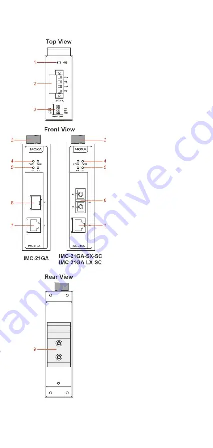
Panel Layout
1.
Shielding Ground
2.
Terminal block for power input
3.
Dip switch
4.
Power LED
5.
Gigabit Copper (G1) / Fiber (G2) Port LED
6.
SFP module slot
7.
10/100/1000BaseT(X) Port
8.
SX/LX Fiber Port, SC connector
9.
DIN rail kit
Page 1: ...2014 Moxa Inc All rights reserved P N 1802000210031 IMC 21GA Hardware Installation Guide Moxa Industrial Media Converter Second Edition October 2014...
Page 2: ...ms are missing or damaged please contact your customer service representative for assistance IMC 21GA media converter Hardware installation guide this guide Warranty card Features The fiber port s con...
Page 3: ...yout 1 Shielding Ground 2 Terminal block for power input 3 Dip switch 4 Power LED 5 Gigabit Copper G1 Fiber G2 Port LED 6 SFP module slot 7 10 100 1000BaseT X Port 8 SX LX Fiber Port SC connector 9 DI...
Page 4: ...rst Be sure to disconnect the power cord before installing and or wiring your IMC 21GA Calculate the maximum possible current in each power wire and common wire Observe all electrical codes dictating...
Page 5: ...to connecting devices ATTENTION This product is intended to be mounted to a well grounded mounting surface such as a metal panel Wiring the Power Inputs The 4 contact terminal block connector on the I...
Page 6: ...e MDI Port Pinouts MDI X Port Pinouts 8 pin RJ45 Pin Signal 1 Tx 2 Tx 3 Rx 6 Rx Pin Signal 1 Rx 2 Rx 3 Tx 6 Tx Straight Through Cable Wiring Cross Over Cable Wiring 1000BaseT X Ethernet Port Connectio...
Page 7: ...two sides of the same line with the same letter A to A and B to B as shown below or A1 to A2 and B1 to B2 LC Port Pinouts LC Port to LC Port Cable Wiring 1000BaseSX LX Fiber Port IMC 21GA SX SC IMC 21...
Page 8: ...for the IMC 21GA use Moxa SFP 1FE Series SFP modules OFF Forces 1000 Mbps on fiber port Note When setting the mode for the IMC 21GA use Moxa SFP 1G Series SFP modules 2 Energy Efficient Ethernet Enabl...
Page 9: ...ps link is inactive Amber On TP port s 10 100 Mbps link is active Blinking Data is being transmitted at 10 100 Mbps Off TP port s 10 100 Mbps link is inactive G2 GREEN On Fiber port s 1000 Mbps link i...
Page 10: ...E 802 3u standard This means that some nodes could be operating at 10 Mbps while at the same time other nodes are operating at 100 Mbps or 1000 Mbps Auto negotiation takes place when an RJ45 cable con...
Page 11: ...ght 170 g Installation DIN rail mounting Environmental Limits Operating Temperature Standard models 10 to 60 C 14 to 140 F Wide temp models 40 to 75 C 40 to 167 F Storage Temperature 40 to 75 C 40 to...
Page 12: ...with the instruction manual may cause harmful interference to radio communications Operation of this equipment in a residential area is likely to cause harmful interference in which case the user will...