Moxa Technologies EtherDevice EDS-P206A-4PoE Series Quick Installation Manual Download Page 8

- 8 - 


WARNING 

Safety First! 
Calculate the maximum possible current in each power wire and 
common wire. Observe all electrical codes dictating the 
maximum current allowable for each wire size. If the current goes 
above the maximum ratings, the wiring could overheat, causing 
serious damage to your equipment. 


You should also pay attention to the following points: 


Use separate paths to route wiring for power and devices. If power 
wiring and device wiring paths must cross, make sure the wires are 
perpendicular at the intersection point. 
NOTE: Do not run signal or communications wiring and power wiring 
in the same wire conduit. To avoid interference, wires with different 
signal characteristics should be routed separately. 


You can use the type of signal transmitted through a wire to 
determine which wires should be kept separate. The rule of thumb is 
that wiring that shares similar electrical characteristics can be 
bundled together. 


Keep input wiring and output wiring separated. 


We strongly advise labeling the wiring to all devices in the system. 

Grounding the EtherDevice Switch 

Grounding and wire routing help limit the effects of noise due to 
electromagnetic interference (EMI). Run the ground connection from the 
ground screw to the grounding surface prior to connecting devices. 


ATTENTION 

This product is intended to be mounted to a well-grounded 
mounting surface such as a metal panel. 


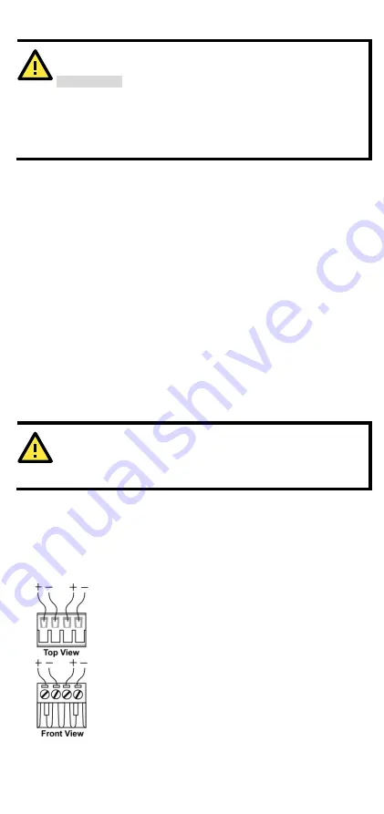
Wiring the Redundant Power Inputs 

The top two contacts and the bottom two contacts of the 4-contact 
terminal block connector on the EDS’s top panel are used for the EDS’s 
two DC inputs. Top and front views of one of the terminal block 
connectors are shown here. 


STEP 1: Insert the negative/positive DC wires into the 
V-/V+ terminals. 
STEP 2: To keep the DC wires from pulling loose, use a 
small flat-blade screwdriver to tighten the wire-clamp 
screws on the front of the terminal block connector. 
STEP 3: Insert the plastic terminal block connector 
prongs into the terminal block receptor, which is 
located on EDS’s top panel. 

Summary of Contents for EtherDevice EDS-P206A-4PoE Series

Page 1: ...m support Moxa Americas Toll free 1 888 669 2872 Tel 1 714 528 6777 Fax 1 714 528 6778 Moxa China Shanghai office Toll free 800 820 5036 Tel 86 21 5258 9955 Fax 86 21 5258 5505 Moxa Europe Tel 49 89 3...

Page 2: ...ty and IP30 metal housing with LED indicators make the plug and play EDS P206A 4PoE switches reliable and easy to use NOTE Throughout this Hardware Installation Guide we use EDS as an abbreviation for...

Page 3: ...s 1 Grounding screw 2 Terminal block for power input P1 P2 3 DIP switches 4 Power input P1 LED 5 Power input P2 LED 6 PoE LED 7 10 100BaseT X port 8 TP port s 10 100 Mbps LED 9 Model name 10 Screw hol...

Page 4: ...EDS P206A 4PoE M SC ST 1 Grounding screw 2 Terminal block for power input P1 P2 3 DIP switches 4 Power input P1 LED 5 Power input P2 LED 6 PoE LED 7 10 100BaseT X port 8 TP port s 10 100 Mbps LED 9 M...

Page 5: ...e EDS P206A 4PoE MM SC ST 1 Grounding screw 2 Terminal block for power input P1 P2 3 DIP Switches 4 Power input P1 LED 5 Power input P2 LED 6 PoE LED 7 10 100BaseT X port 8 TP port s 10 100 Mbps LED 9...

Page 6: ...e box If you need to reattach the DIN Rail attachment plate make sure the stiff metal spring is situated towards the top as shown in the figures below STEP 1 Insert the top of the DIN Rail into the sl...

Page 7: ...the screws into the wall make sure the screw head and shank size are suitable by inserting the screw into one of the keyhole shaped apertures of the wall mounting plates Do not screw the screws in com...

Page 8: ...s can be bundled together Keep input wiring and output wiring separated We strongly advise labeling the wiring to all devices in the system Grounding the EtherDevice Switch Grounding and wire routing...

Page 9: ...thernet cables MDI Port Pinouts MDI X Port Pinouts 8 pin RJ45 Pin Signal 1 Tx 2 Tx 3 Rx 6 Rx Pin Signal 1 Rx 2 Rx 3 Tx 6 Tx PoE 10 100BaseT X Ethernet Port Connection PoE 10 100BaseT X ports located o...

Page 10: ...ou are connecting devices I and II contrary to electrical signals optical signals do not require a circuit in order to transmit data Consequently one of the optical lines is used to transmit data from...

Page 11: ...ce fails the other live source acts as a backup and automatically supplies all of the EDS s power needs DIP Switch Settings The default setting for each DIP Switch is OFF The following table explains...

Page 12: ...port s 100 Mbps link is inactive PoE AMBER On The PoE device is connected by the IEEE 802 3af standard Blinking The PoE power is shut off because there is insufficient power Off No PoE power output o...

Page 13: ...packet arrives at one of the switched ports a decision is made to either filter or forward the packet Packets with source and destination addresses belonging to the same port segment will be filtered...

Page 14: ...rd Total Power Budget For the total power budget the EDS P206A 4PoE will have 62 W at 12 17 VDC input and 120 W at 18 57 VDC input The total power budget is the total amount of reserved PoE power base...

Page 15: ...VDC power input PoE Output Power 15 4 W for 802 3af 30 W for 802 3at PoE Output Current 350 mA for 802 3af 600 mA for 802 3at Overload Current Protection at the port Supported PoE Pinout Mode A Pair 1...

Page 16: ...185 F Ambient Relative Humidity 5 to 95 non condensing Regulatory Approvals Safety UL508 EMI FCC Part 15 CISPR EN55032 class A EMS IEC 61000 4 2 ESD Contact 6 kV Air 8 kV IEC 61000 4 3 RS 20 V m 80 MH...

Reviews: