Moxa Technologies EtherDevice EDS-G508E Hardware Installation Manual Download Page 10


- 10 - 

USB Console Connection 

The EDS-G500E series has one USB console port (type B connector), 
located on the top panel. Use the USB cable (provided in the product 
package) to connect the EDS-G500E's console port to your PC's USB port 
and install the USB driver (available in the software CD) on the PC. You 
may then use a console terminal program, such as Moxa PComm Terminal 
Emulator, to access the EDS-G500E’s console configuration utility. 

USB Console Port (Type B Connector) Pinouts 


Pin 

Description 

D– (Data -) 

VCC (+5V) 

D+ (Data+) 

GND (Ground) 


USB Storage Connection 

The EDS-G500E series has one USB storage port (type A connector) on 
the front panel. Use Moxa ABC-02-USB-T automatic backup configurator 
to connect the EDS-G500E's USB storage port for configuration backup, 
firmware upgrade or system log file backup. 

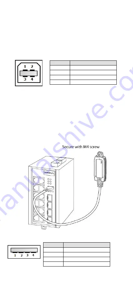
ABC-02-USB Installation 

Plug the ABC-02-USB into the USB storage port of the Moxa EDS-G500E 
series. Securing the ABC-02-USB on the wall with an M4 screw is 
suggested. 


USB Storage Port (Type A Connector) Pinouts 


Pin 

Description 

VCC (+5V) 

D– (Data -) 

D+ (Data+) 

GND (Ground) 


Summary of Contents for EtherDevice EDS-G508E

Page 1: ...2013 Moxa Inc All rights reserved P N 1802005000020 EDS G500E Series Hardware Installation Guide Moxa EtherDevice Switch First Edition July 2013...

Page 2: ...tallation guide Documentation and software CD Moxa product warranty statement USB cable Protective caps for unused ports Features Up to 12 10 100 1000BaseT X ports and 4 100 1000BaseSFP ports Turbo Ri...

Page 3: ...ports EDS G508E 1 to 8 EDS G512E 4GSFP 1 to 8 EDS G516E 4GSFP 1 to 12 4 System status LED STATE LED indicator PWR1 LED indicator PWR2 LED indicator FAULT LED indicator MSTR HEAD LED indicator CPLR TA...

Page 4: ...t 3 DIP switches for Turbo Ring Ring Master and Ring Coupler 4 Grounding screw 5 4 pin terminal block for digital input and power input 2 6 4 pin terminal block for relay output and power input 1 Rear...

Page 5: ...5 Mounting Dimensions Unit mm inch...

Page 6: ...ng rails that meet the EN 60715 standard Installation STEP 1 Insert the upper lip of the DIN rail into the DIN rail mounting kit STEP 2 Press the EDS G500E series towards the DIN rail until it snaps i...

Page 7: ...size are suitable by inserting the screw through one of the keyhole shaped apertures of the Wall Mounting Plates Do not screw the screws in all the way leave about 2 mm to allow room for sliding the w...

Page 8: ...al characteristics should be routed separately You can use the type of signal transmitted through a wire to determine which wires should be kept separate The rule of thumb is that wiring that shares s...

Page 9: ...is located on the EDS G500E s top panel Wiring the Digital Inputs The EDS G500E series has one set of digital input DI The DI consists of two contacts of the 4 pin terminal block connector on the EDS...

Page 10: ...USB Console Port Type B Connector Pinouts Pin Description 1 D Data 2 VCC 5V 3 D Data 4 GND Ground USB Storage Connection The EDS G500E series has one USB storage port type A connector on the front pan...

Page 11: ...ently one of the optical lines is used to transmit data from device I to device II and the other optical line is used transmit data from device II to device I for full duplex transmission Remember to...

Page 12: ...s Turbo Ring or 50 ms Turbo Ring V2 compared to a 3 to 5 minute recovery time for commercial switches decreasing the possible loss caused by network failures in an industrial setting There are 4 Hardw...

Page 13: ...s range to be the Ring Master If you accidentally enable more than one EDS G500E series to be the Ring Master these EDS G500E series switches will auto negotiate to determine which one will be the Rin...

Page 14: ...aster of this Turbo Ring 2 This switch is set as a Member of the Turbo Chain CPLR TAIL Green On 1 The switch s coupling function is enabled to form a back up path 2 When it s set as the Tail of the Tu...

Page 15: ...MIB RMON MIB Group 1 2 3 9 Flow Control IEEE 802 3x flow control back pressure flow control Interface RJ45 Ports 8 EDS G508E EDS G512E 4GSFP or 12 EDS G516E 4GSFP 10 100 1000BaseT X Fiber Ports 4 por...

Page 16: ...ry Approvals Safety UL 508 EMI FCC Part 15 Subpart B Class A EN 55022 Class A EMS EN 61000 4 2 ESD Level 4 EN 61000 4 3 RS Level 3 EN 61000 4 4 EFT Level 4 EN 61000 4 5 Surge Level 4 EN 61000 4 6 CS L...

Reviews: