


- 8 -
Grounding the Moxa EDS-528E
Grounding and wire routing help limit the effects of noise due to
electromagnetic interference (EMI). Run the ground connection from the
ground screw to the grounding surface prior to connecting devices.
ATTENTION
This product is intended to be mounted to a well-grounded
mounting surface such as a metal panel.
Wiring the Relay Contact
The EDS-528E series has one relay output. This relay contact uses two
contacts of the terminal block on the EDS-528E’s top panel. Refer to the
next section for detailed instructions on how to connect the wires to the
terminal block connector, and how to attach the terminal block connector
to the terminal block receptor. In this section, we illustrate the meaning
of the two contacts used to connect the relay contact.
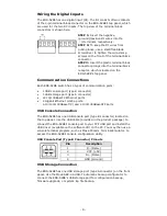
FAULT:
The two contacts of the 4-pin terminal
block connector are used to detect
user-configured events. The two wires
attached to the fault contacts form an
open circuit when a user-configured
event is triggered. If a user-configured
event does not occur, the fault circuit
remains closed.
Wiring the Redundant Power Inputs
The EDS-528E has two sets of power inputs—power input 1 and power
input 2. The top view of the terminal block connectors is shown here.
STEP 1:
Insert the negative/positive DC
wires into the V-/V+ terminals,
respectively.
STEP 2:
To keep the DC wires from
pulling loose, use a small flat-blade
screwdriver to tighten the wire-clamp
screws on the front of the terminal block
connector.
STEP 3:
Insert the plastic terminal block
connector prongs into the terminal block
receptor, which is located on the
EDS-528E’s top panel.


