– 4 –
– 5 –
– 6 –
www.moxa.com/support
The Americas: +1-714-528-6777 (toll-free: 1-888-669-2872)
Europe: +49-89-3 70 03 99-0
Asia-Pacific: +886-2-8919-1230
China: +86-21-5258-9955 (toll-free: 800-820-5036)
2012 Moxa Inc. All rights reserved.
Connecting to a Display
Your DA-681 embedded computer comes with a D-Sub 15-pin
female connector to connect to the VGA monitor. Be sure to
remove the power before you connect or disconnect the monitor
cable.
Connecting to a Keyboard and Mouse
The DA-681 comes with a PS/2 mini-DIN connector to connect a
PS/2 keyboard and PS/2 mouse. This 6-pin mini-DIN connector’s
pin assignments are shown below.
Pin No.
Signal Definition
1
PS/2 Keyboard Data
2
PS/2 Mouse Data
3
GND
4
VCC
5
PS/2 Keyboard Clock
6
PS/2 Mouse Clock
Use the Y-type cable to convert the mini-DIN connector into two
6-pin mini-DIN connectors to connect both a PS/2 keyboard and
PS/2 mouse at the same time. (The Y-type cable is not included in
the accessory package. It should be purchased separately. You
may also use the USB ports to connect your USB-based keyboard
and mouse.)
Serial Ports
The DA-681 offers six RS-232 ports with DB9 connectors and eight
RS-485 ports with Terminal Blocks. The pin assignments for the
ports are shown in the following table:
Pin
RS-232
RS-485
(2-wire)
1
DCD
---
2
RxD
---
3
TxD
Data(+)
4
DTR
Data(-)
5
GND
GND
6
DSR
---
7
RTS
---
8
CTS
---
Ethernet Ports
The DA-681 provides 6 10/100 Mbps Ethernet ports with RJ45
connectors. The pin assignments for the ports are shown in the
following table:
Pin No.
Signal Definition
1
TX+
2
TX-
3
RX+
4
---
5
---
6
RX-
7
---
8
---
The LEDs on the RJ45 port indicate the following conditions:
LED
Color
Description
RJ45 Connector
Green
100 Mbps Ethernet mode
Yellow
10 Mbps Ethernet mode
Off
No activity
The default IP addresses and netmasks of the Ethernet ports are as
follows:
Default IP Address
Netmask
LAN 1
192.168.3.127
255.255.255.0
LAN 2
192.168.4.127
255.255.255.0
LAN 3
192.168.5.127
255.255.255.0
LAN 4
192.168.6.127
255.255.255.0
LAN 5
192.168.7.127
255.255.255.0
LAN 6
192.168.8.127
255.255.255.0
4.
Configuring the Ethernet Interface
Linux users should follow these steps:
If you use the console cable to configure Network settings for the
first time, use the following commands to edit the interfaces file:
#ifdown –a
//Disable LAN1~LAN6 interface first, before you
reconfigure the LAN settings. LAN1 = eth0, LAN2 = eth1
and so on//
#vi /etc/network/interfaces
//check the LAN interface first//
After the boot setting of the LAN interface has been modified, use
the following commands to activate the LAN settings immediately:
#sync; ifup –a
WinXPE users should follow these steps:
Step 1: Go to
Start
Settings
Network Connections
.
Step 2: In the screen of
Local Area Connection Properties
,
click
Internet Protocol (TCP/IP)
and then select
Properties
.
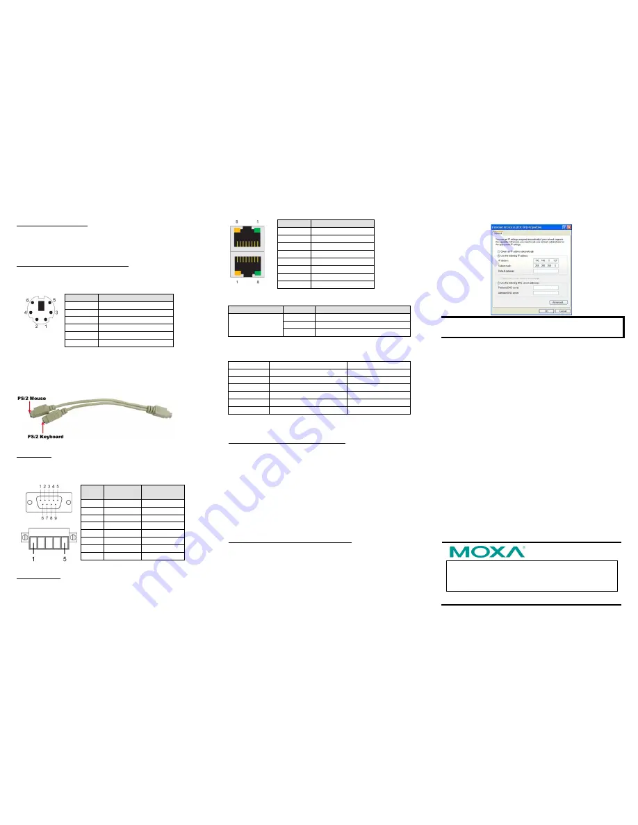
Step 3: Click
OK
after inputting the proper IP address and
netmask.
NOTE
Refer to the User’s Manual for additional configuration
information.


