

—
4
—
—
5
—
—
6
—
Grounding CN2510-16/8-48V:
V+ V-
SG
ON
OFF
Grounding and wire routing helps limit the effects of noise
due to electromagnetic interference (EMI). Run the ground
connection from the
ground screw to the grounding
surface prior to connecting devices. The Shielded Ground
(sometimes called Protected Ground) contact is the second
contact from the right of the 5-pin power terminal block
connector located on the rear panel of CN2510-8/16-48V.
Connect the SG wire to the Earth ground.
4.
Connecting to the Network
Connect one end of the Ethernet cable to CN2510’s 10/100M Ethernet
port and the other end of the cable to the Ethernet network. There are 2
LED indicators located on the top left and right corners of the Ethernet
connector. If the cable is properly connected, CN2510 will indicate a valid
connection to the Ethernet in the following ways:
LAN
The top right corner LED indicator maintains a solid
green color when the cable is properly connected to a
100 Mbps Ethernet network.
LAN
The top left corner LED indicator maintains a solid
orange color when the cable is properly connected to
a 10 Mbps Ethernet network.
5.
Connecting to a Serial Device
Connect the serial data cable between CN2510 and the serial device.
6.
Connecting to a Console
A console is a combination of keyboard and monitor that are used to
configure settings and to monitor the status of your system. If you do not
have a network environment, use a terminal, a PC running UNIX, or a PC
with terminal emulation software (e.g., HyperTerminal in Windows;
PComm by Moxa). Use an RJ45-to-DB25 or RJ45-to-DB9 cable to
connect the terminal to the console socket. Refer to the CN2510 Async
Server User’s Manual for more details.
5. Software Installation
Entering the Console Utility
The Console Utility is the main application needed to set up the server/port
configuration, and to execute utilities such as ping, diagnosis, monitor, and
upgrade. There are two ways to enter the Console Utility. One is to use
terminal emulation through a console terminal, and the other is to telnet from
a network terminal.
Refer to the CN2510 Async Server User’s Manual for more details.
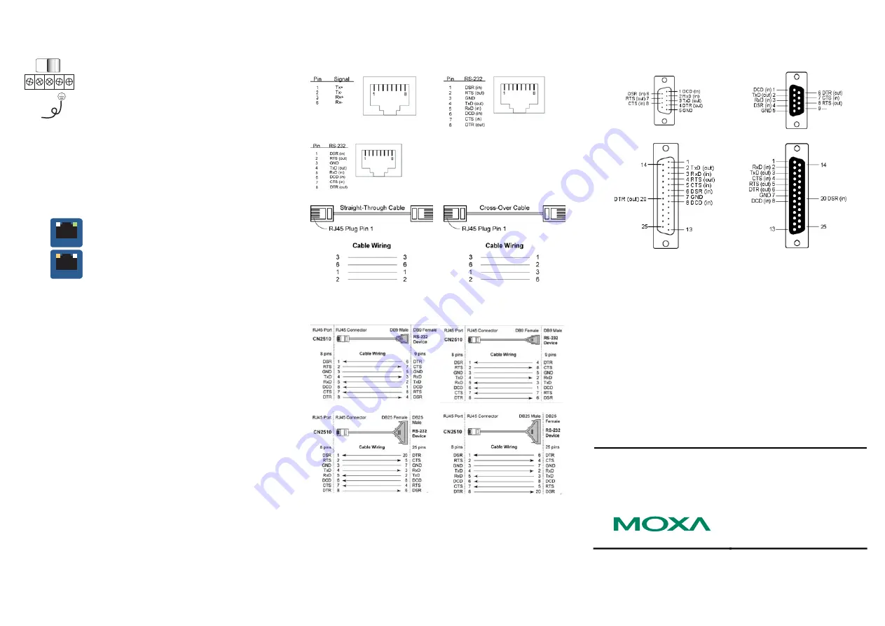
6. Pin Assignments and Cable Wiring
10/100BaseTX Port Pinouts
Console Port Pinouts
Async RS-232 Port Pinouts
10/100BaseTX Cable Wiring
Async RS-232 Cable Wiring:
Note: The following cables are optional accessories.
CBL-RJ45M9-150 CBL-RJ45F9-150
CBL-RJ45F25-150 CBL-RJ45M25-150
DB9 and DB25 connector pinouts:
The following figures illustrate standard connector pinouts. However, pinouts
for serial devices differ from manufacturer to manufacturer. Refer to the
serial device’s user’s manual for the exact pinouts of your device.
DB9 Male Connector
DB9 Female Connector
DB25 Male Connector
DB25 Female Connector
7. Environmental Specifications
Power requirements
Power Input
Power Consumption
CN2510-8/16
CN2510-8/16-48V
100 to 240 VAC, 47 to 63 Hz, or 12-48 VDC
235 mA for 100V, 145 mA for 240V
250 mA (at 48V max.)
Operating temp.
0 to 55°C (32 to 131°F)
Operating humidity
5 to 95% RH
Dimensions (W×D×H)
190 × 44.5 × 478 mm (including ears)
190 × 44.5 × 440 mm (without ears)
Serial line protection
15 KV ESD for all signals
Magnetic isolation
1.5 KV for Ethernet
Power line protection
4 KV Burst (EFT), EN61000-4-4
2 KV Surge, EN61000-4-5
Regulatory approvals
FCC Class A, CE Class A, UL, CUL, TÜV
Copyright
2004
Moxa Technologies Co., Ltd.
All rights reserved.
Reproduction without permission is prohibited.
Tel: +886-2-8919-1230
Fax: +886-2-8919-1231
www.moxa.com
[email protected]


