background image

- 5 - 

Wall Mounting (optional) 

For transportation applications that require an EN50155 certification 
report, you should purchase the optional wall mount for the AWK-5222, 
since the wall mount has passed EN50155 testing. The wall mount is also 
convenient for other applications that require mounting the AWK-5222 to 
a wall. 

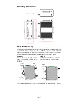
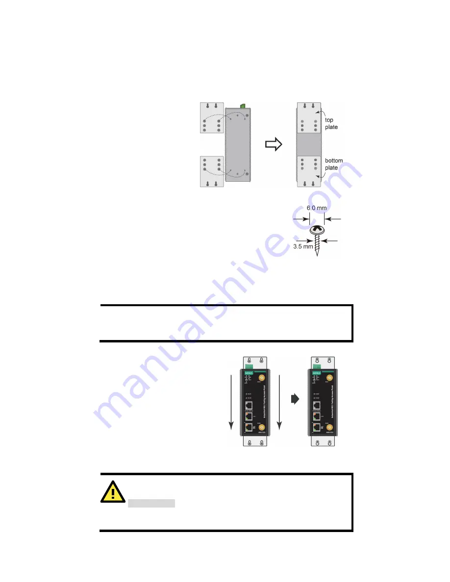
STEP 1: 

Remove the aluminum 
DIN-rail attachment plate 
from the AWK-5222, and 
then attach the 
wall-mounting plates with 

M3

 screws, as shown in the 

adjacent diagrams. 


STEP 2: 

Mounting the AWK-5222 to a wall requires 4 screws. 
Use the AWK-5222 device, with wall-mounting plates 
attached, as a guide to mark the correct locations of 
the 4 screws. The heads of the screws should be less 
than 6.0 mm in diameter, and the shafts should be 
less than 3.5 mm in diameter, as shown in the figure 
at the right. 


Do not drive the screws in all the way into the wall—leave a space of about 
2 mm to allow room for sliding the wall-mounting panel between the wall 
and the screws. 

NOTE 

Test the screw head and shank size by inserting the screws into 
one of the keyhole shaped apertures of the wall-mounting plates 
before attaching the plates to the wall. 


STEP 3: 

Once the screws are fixed into the 
wall, insert the four screw heads 
through the large opening of the 
keyhole-shaped apertures, and 
then slide the AWK-5222 
downwards, as indicated to the 
right. Tighten the four screws for 
added stability. 


Wiring Requirements 


WARNING 

Safety First!


Be sure to disconnect the power cord before installing and/or 
wiring your Moxa AWK-5222. 


Summary of Contents for AirWorks AWK-5222

Page 1: ...a Americas Toll free 1 888 669 2872 Tel 1 714 528 6777 Fax 1 714 528 6778 Moxa China Shanghai office Toll free 800 820 5036 Tel 86 21 5258 9955 Fax 86 21 5258 5505 Moxa Europe Tel 49 89 3 70 03 99 0 Fax 49 89 3 70 03 99 99 Moxa Asia Pacific Tel 886 2 8919 1230 Fax 886 2 8919 1231 Moxa India Tel 91 80 4172 9088 Fax 91 80 4132 1045 2016 Moxa Inc All rights reserved ...

Page 2: ...older with one screw Documentation and software CD Quick installation guide printed Warranty card Installation and Configuration Before installing the AWK 5222 make sure that all items in the Package Checklist are in the box In addition you will need access to a notebook computer or PC equipped with an Ethernet port The AWK 5222 has a default IP address that you must use when connecting to the dev...

Page 3: ...AWK 5222 By default the AWK 5222 s operation mode is set to Wireless Redundancy You can change the setting in Wireless Settings Operation mode if you would like to use the Wireless Bridge or AP Client mode NOTE To make the change effective you must click Save Configuration to save the change or Restart Save and Restart button to apply all changes Panel Layout of the AWK 5222 1 Grounding screw 2 Te...

Page 4: ...to reattach the DIN rail attachment plate to the AWK 5222 make sure the stiff metal spring is situated towards the top as shown in the figures below STEP 1 Insert the top of the DIN rail into the slot just below the stiff metal spring STEP 2 The DIN rail attachment unit will snap into place as shown below To remove the AWK 5222 from the DIN rail simply reverse Steps 1 and 2 ...

Page 5: ...heads of the screws should be less than 6 0 mm in diameter and the shafts should be less than 3 5 mm in diameter as shown in the figure at the right Do not drive the screws in all the way into the wall leave a space of about 2 mm to allow room for sliding the wall mounting panel between the wall and the screws NOTE Test the screw head and shank size by inserting the screws into one of the keyhole ...

Page 6: ...l transmitted through a wire to determine which wires should be kept separate The rule of thumb is that wiring with similar electrical characteristics can be bundled together Keep input wiring and output wiring separate It is strongly advised that you label wiring to all devices in the system when necessary ATTENTION This product is intended to be supplied by a Listed Power Unit marked Class 2 or ...

Page 7: ...uipment is recommended to isolate the transient effect and to ensure a stable power input for the AWK Installations with Cable Extended Antennas for Outdoor Applications If the antenna or the AWK device is installed outdoors or in an open air setting proper lightning protection is required to prevent direct lightning strikes on the AWK device In order to prevent coupling currents from nearby light...

Page 8: ... views of the terminal block connector is shown here STEP 1 Insert the negative positive DC wires into the V V terminals STEP 2 To keep the DC wires from pulling loose use a small flat blade screwdriver to tighten the wire clamp screws on the front of the terminal block connector STEP 3 Insert the plastic terminal block connector prongs into the terminal block receptor which is located on the AWK ...

Page 9: ...I1 and DI2 Each DI comprises two contacts of the 10 pin terminal block connector on the AWK 5222 s top panel You can refer to the Wiring the Redundant Power Inputs section for detailed instructions on how to connect the wires to the terminal block connector and how to attach the terminal block connector to the terminal block receptor Cable Holder Installation Optional You can attach the cable hold...

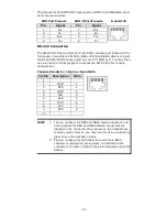
Page 10: ...sole terminal program to access the AWK 5222 for console configuration Console Pinouts for 10 pin or 8 pin RJ45 10 Pin Description 8 Pin 1 2 DSR 1 3 RTS 2 4 GND 3 5 TxD 4 6 RxD 5 7 DCD 6 8 CTS 7 9 DTR 8 10 NOTE 1 The pin numbers for DB9 and DB25 male connectors and hole numbers for DB9 and DB25 female connectors are labeled on the connector strip However the numbers are typically quite small so yo...

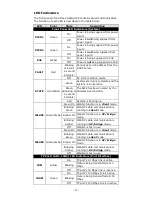
Page 11: ...ntervals The AWK has been located by the Wireless Search Utility Red System is booting up WLAN1 Green Amber Green On WLAN1 function is in client mode Blinking Green WLAN1 s data communication is running in client mode Amber On WLAN1 function is in AP bridge mode Blinking Amber WLAN1 s data communication is running in AP bridge mode Off WLAN1 is not in use WLAN2 Green Amber Green On WLAN2 function ...

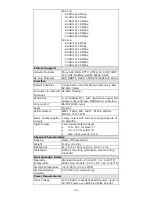
Page 12: ...12 to 2 462 GHz 11 channels 5 18 to 5 24 GHz 4 channels EU 2 412 to 2 472 GHz 13 channels 5 18 to 5 24 GHz 4 channels JP 2 412 to 2 472 GHz 13 channels OFDM 2 412 to 2 484 GHz 14 channels DSSS 5 18 to 5 24 GHz 4 channels for W52 Security SSID broadcast enable disable Firewall for MAC IP Protocol Port based filtering 64 bit and 128 bit WEP encryption WPA WPA2 Personal and Enterprise IEEE 802 1X RAD...

Page 13: ...ection Console Port RS 232 RJ45 type Reset Present LED Indicators PWR1 PWR2 PoE FAULT STATE WLAN1 WLAN2 10M 100M Alarm Contact digital output 1 relay output with current carrying capacity of 1A 24VDC Digital Inputs 2 electrically isolated inputs 13 to 30 V for state 1 3 to 30 V for state 0 Max input current 8 mA Physical Characteristics Housing Metal IP30 protection Weight 1100 g 2 43 lb Dimension...

Page 14: ...WK 5222 is NOT a portable mobile device and should be located at least 20 cm away from the human body The AWK 5222 is NOT designed for the general public A well trained technician is required to deploy the AWK 3191 units and safely establish a wireless network ATTENTION Use the antennas correctly Two dual band 2 4 GHz 5 GHz antennas are included with the product Either antenna can be installed in ...

Reviews: