


INSTALLATIONS
12
IB970 User’s Manual
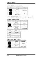
JP11: LVDS Panel Power Selection
JP11
Setting
Panel Voltage
Pin 1-2
Short/Closed
3.3V (default)
Pin 2-3
Short/Closed
5V
JP12: LVDS EEPROM Flash Connector (factory use only)
JP14: BL Voltage Setting
JP14
Setting
Function
Pin 1-2
Short/Closed
+3.3V
Pin 3-4
Short/Closed
+5V
Pin 5-6
Short/Closed
+12V(Default)
JP15: BL_ADJ_LEVEL Setting
JP15
Function
Open
3.3V
Close
5V (default)
JBAT1: Clear CMOS Contents
JBAT1
Setting
Function
Pin 1-2
Short/Closed
Normal
Pin 2-3
Short/Closed
Clear CMOS
Summary of Contents for IB970
Page 1: ...IB970 3rd Gen Intel CoreTM i7 i5 B75 PCH Full Size CPU Card USER S MANUAL Version 1 0 ...
Page 4: ...iv IB970 User s Manual This page is intentionally left blank ...
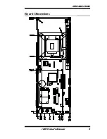
Page 9: ...INTRODUCTION IB970 User s Manual 5 Board Dimensions ...
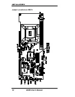
Page 14: ...INSTALLATIONS 10 IB970 User s Manual Jumper Locations on IB970 ...
Page 19: ...INSTALLATIONS IB970 User s Manual 15 Connector Locations on IB970 ...
Page 26: ...INSTALLATIONS 22 IB970 User s Manual This page is intentionally left blank ...
Page 52: ...BIOS SETUP 48 IB970 User s Manual This page is intentionally left blank ...
Page 72: ...DRIVER INSTALLATION 68 IB970 User s Manual This page is intentionally left blank ...