background image

22


       June 22, 2006  

Disassembly

 W220

PRELIMINARY

W220

Removing and Replacing the Battery

1.

Remove the battery door as described in the procedures.

2.

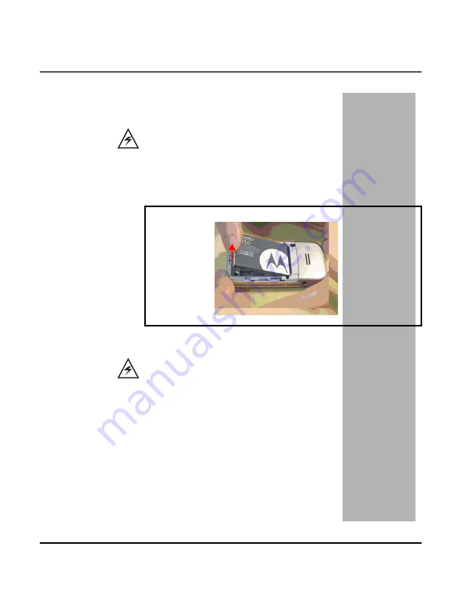
Raise and remove the battery at the direction illustrated in the Figure 6

.

All batteries can cause property damage and/or bodily injury such as burns if a conductive 
material such as jewelry, keys, or beaded chains touch exposed terminals. The conductive 
material may complete an electrical circuit (short circuit) and become quite hot. Exercise care 
in handling any charged battery, particularly when placing it inside a pocket, purse, or other 
container with metal objects.

Figure 6. Removing the Battery

There is a danger of explosion if the Lithium Ion battery is replaced incorrectly. Replace only 
with the same type of battery or equivalent as recommended by the battery manufacturer. 
Dispose of used batteries according to the manufacturer’s instructions.

Summary of Contents for W220

Page 1: ...PRELIMINARY Level 1 2 Service Manual W220 Dual Band Wireless Telephone W 220 GSM 900 1800MHz ...

Page 2: ......

Page 3: ...y Door 20 Removing and Replacing the Battery 22 Removing and Replacing the Lower Housing Cover 24 Removing and Replacing the PCBA 26 Removing and Replacing the Antenna Carrier 28 Removing and Replacing the Vibrator and battery connector 29 Removing and Replacing the Plate Latch Button Spring and Latch button 30 Removing and Replacing the Speaker 31 Removing and Replacing the LCM shielding cover 32...

Page 4: ...June 22 2006 3 Level Service Manual PRELIMINARY Accessories 42 Index 43 ...

Page 5: ... is assigned to the chassis or kit affected for example A B or C and so on The chassis or kit number complete with revision number is imprinted during production The revision letter is an integral part of the chassis or kit number and is also listed on schematic diagrams and printed circuit board layouts Regulatory Agency Compliance This device complies with Part 15 of the FCC Rules Operation is s...

Page 6: ...l contains mechanical service information required for the equipment described and is current as of the printing date Audience This document aids service personnel in testing and repairing W220 telephones Service personnel should be familiar with electronic assembly testing and troubleshooting methods and with the operation and use of associated test equipment Scope This manual provides basic info...

Page 7: ...ll be repaired but not refurbished as standard Appointed Motorola Service Hubs will perform warranty and non warranty field service for level 2 assemblies and level 3 limited PCB component Motorola High Tech Centers will perform level 4 full component repairs Customer Support Customer support is available through dedicated Call Centers and in country help desks Product Service training should be a...

Page 8: ...el number or other related major assembly along with a description of the related major assembly and of the component in question In the U S A to contact Motorola Inc on your TTY call 800 793 7834 Accessories and Aftermarket Division AAD Replacement parts test equipment and manuals can be ordered from AAD For EMEA spare parts call 49 461 803 1638 For Asia spare parts call 65 648 62995 U S A Outsid...

Page 9: ...t Type Clam Shell phone with built in antenna Messaging SMS MMS EMS Antenna Internal type I O Bus Connector Audio Jack Frequency Range EGSM 880 915 MHz Tx 925 960 MHz Rx DCS 1710 1785 MHz Tx 1805 1880 MHz Rx Channel Spacing 200 KHz Channels EGSM 174 DCS 374 carriers with 8 channels per carrier Modulation GMSK at BT 0 3 Transmitter Phase Accuracy 5 degrees RMS 20 degrees peak Duplex Spacing EGSM 45...

Page 10: ...Function Specification Receive Sensitivity GSM 106 dBm DSC 105 dBm Rx Bit Error Rate 100k bits Type II 2 Channel Hop Time 500 microseconds Time to Camp Approximately 5 10 seconds Speech Coding Function Specification Speech Coding Type Regular pulse excitation Linear predictive coding with long term prediction RPE LPC with LTP Bit Rate 13 0 kbps Frame Duration 20 ms Block Length 260 bits Classes Cl...

Page 11: ...rbonate plastic The display and speaker as well as the 21 key keypad transceiver printed circuit board PCB microphone charger and headphone connectors and power button are contained within the clamshell form factor housing The user replaceable 850 mAh Lithium Ion LiIon battery provides up to 497 minutes of talk time with up to 293 hours of standby time1 The phone accepts 3V mini subscriber identit...

Page 12: ... number and connection type Simplified Text Entry iTAP predictive text entry Press a key to generate a character and a dynamic dictionary uses this to build and display a set of word or name options The iTAP feature may not be available on the phone in all languages Caller Line Identification Upon receipt of a call the calling party s phone number is compared to the phonebook If the number matches...

Page 13: ...g The chat messaging feature provides a constant WAP connection through GPRS to carrier service center or factory flexed WAP site The specific site can also be entered by the user Chat messaging is a carrier option Personal Information Management The W220 telephone contains a built in calendar with datebook reminders and phonebook Other Features Detailed descriptions of the other features can be f...

Page 14: ...telephones controls are located on the front and side of the device and on the keyboard as shown in Figure 1 Indicators in the form of icons are displayed on the LCD see Figure 2 Figure 1 W220 Telephone Controls Locations Earpiece Main Display Right Soft Key Left Soft Key OK Key 5 Way Navigation Key l or Power Key End key Send Key Microphone 1 2 W220 ...

Page 15: ...ion When the up down side key voice activation key is held down from a idle display provides a shortcut to voice dialing and voice feature launcher Liquid Crystal Display LCD The LCD provides an 832 square millimetremulticolorbacklit color display with user adjustable contrast settings for optimum readability in all light conditions The large bit mapped 128 x 128 pixel display includes up to 4 lin...

Page 16: ...available 3 bars maximum Bars differ in color by power level green orange red The icon flashes when battery power is near empty Roaming Indicates you are on another network Voice Call Active Indicates a call is in progress New SMS Message Indicates new unread SMS message s The icon flashes when the phone s memory which stores SMS messages is full You must read new SMS messages to receive more SMS ...

Page 17: ...Indicates ringer is turned off GPRS Mode Indicates your service provider supports GPRS GPRS Data Call Active Indicates you are surfing over the GPRS network Online Chat Active Indicates you open Chatroom to have an online chat Line 1 Line 2 Indicates the telephone line you are using Call Waiting Indicates a call is waiting to answer Call Diverting Indicates all of your incoming calls will be trans...

Page 18: ...a Picture Sounds FM Radio Web Access Browser Web shortcuts Go to URL Web Sessions Download settings Web Setting Games apps Five bal Flying Sound effect Settings Personalize Home Screen Color Style Wallpaper Screen Saver Quick dial Ring Styles Style Soft Detail Call Forward When Busy No Reply Not Reachable Not Available All Calls Cancel All In Call Setup In Call Timer Call Cost Setup Show Number Ca...

Page 19: ... and Low Battery Battery Removal Removing the battery causes the phone to shut down immediately and loose any pending work partially entered phonebook entries or outgoing messages for example Operation For detailed operating instructions refer to the appropriate User Guide listed in the Related Publications section toward the end of this manual All batteries can cause property damage and or bodily...

Page 20: ...attery and power phone 0180386A82 Antistatic Mat Kit includes 66 80387A95 antistatic mat 66 80334B36 ground cord and 42 80385A59 wrist band Provides protection from damage to phone caused by electrostatic discharge ESD 8102430Z04 GSM DCS Test SIM Used to enable manual test mode 6680388B67 Disassembly tool plastic with flat and pointed ends manual opening tool Used during assembly disassembly 66803...

Page 21: ...y door forward to the direction illustrated in Figure 4 2 Completely remove the battery door Many of the integrated devices used in this phone are vulnerable to damage from electrostatic discharge ESD Ensure adequate static protection is in place when handling shipping and servicing any internal components Avoid stressing the plastic in any way to avoid damage to either the plastic or internal com...

Page 22: ... replace the 7 side hooks should be aligned with the holes on the lower housing cover in Figure 5 Slide the battery door in the direction shown until it clicks into place and hear a click sound Then completely replace the battery door Figure 5 Replacing the Battery Door ...

Page 23: ...ded chains touch exposed terminals The conductive material may complete an electrical circuit short circuit and become quite hot Exercise care in handling any charged battery particularly when placing it inside a pocket purse or other container with metal objects Figure 6 Removing the Battery There is a danger of explosion if the Lithium Ion battery is replaced incorrectly Replace only with the sa...

Page 24: ...isassembly PRELIMINARY 3 To replace insert battery with an small angle into handset and press battery downward Make sure the battery latch can lock battery 4 Replace the battery door as described in the procedures Figure 7 Replacing the Battery ...

Page 25: ... Remove the battery door and battery as described in the procedures 2 Sequentialy remove 1 2 3 4 screwa with a 6 corner star T5 screwdriver as shown in Figure 8 3 Release the hook between Case C D by fingernail as shown in Figure 9 Figure 8 Removing 4 Screws Figure 9 Removing the hooks 1 2 3 4 ...

Page 26: ...ower housing cover to the phone Press the lower housing cover into place allowing the housing latches on each side of the phone to snap into position 6 Use 4 screws T5 to fasten the lower housing cover to the front housing cover with 9 Ncm torque moment 7 Replace the battery and battery door as described in the procedures Figure 10 Removing the Lower Housing Cover 1 2 ...

Page 27: ... the battery door battery and lower housing cover as described in the procedures 2 Remove the volume key PCBA from the Housing C with a tweezer as shown in Figure 11 3 Remove the BTB FPC connector from Main PCBA with a tweezer as shown in Figure 12 Figure 11 Removing Volume Key PCBA Figure 12 Removing BTB FPC Connector ...

Page 28: ...e Key PCBA into the Housing C Removing and Replacing the PCBA 1 Remove the battery door battery lower housing cover volume key PCBA and BTB FPC as described in the procedures 2 Press the hook and release PCBA from lower housing cover as shown in Figure 15 Figure 13 Removing Volume Key PCBA Figure 14 Removing BTB FPC Connector ...

Page 29: ...June 22 2006 Disassembly W220 PRELIMINARY 3 Put Main PCBA into the Housing C as Figure 16 17 Figure 15 Removing PCBA from lower housing cover Figure 16 Replacing PCBA to lower housing cover Press the hook ...

Page 30: ...To replace align the PCBA to the phone and then press it into place 5 Hook PCBA to lower housing cover 6 Replace the lower housing cover volume key BTB FPC battery and battery door as described in the procedures Figure 17 Replacing the Main PCBA to lower housing cover ...

Page 31: ...place align the position holes on antenna carrier onto the lower phone case 4 Replace the PCBA lower housing cover battery and battery door as described in the procedures Removing and Replacing the Speaker Box 1 Remove the battery door battery lower housing cover lower PCB antenna carrier as described in the procedures 2 Remove the Speaker Box from the Main PCBA as shown in Figure 19 Figure 18 Rem...

Page 32: ... Replacing the RF Cap Vibrator and battery connector 1 Remove the battery door battery lower housing cover PCBA antenna carrier as described in the procedures 2 Remove RF Cap Vibrator and Battery Connector from Housing D as shown in Figure 21 3 To replace align the lower housing cover and press into place 4 Replace the antenna carrier PCBA lower housing cover battery and battery door as described ...

Page 33: ... vibrator and battery connector as described in the procedures 2 Remove the keypad and hinge stopper from Housing C as shown in Figure 22 3 To replace put keypad into the Housing C 4 Replace the antenna carrier PCBA lower housing cover battery and battery door as described in the procedures Figure 22 Removing the Keypad and Hinge Stopper Figure 23 Replacing the Keypad and Hinge Stopper ...

Page 34: ...eaker hook onto the Speaker Box 4 Replace the speaker box antenna carrier PCBA lower housing cover battery and battery door as described in the procedures Removing and Replacing the Screw Cover Cap Screws from Housing B 1 Remove the battery door battery lower housing cover lower PCB antenna carrier as described in the procedures 2 Remove the Screw Cover Cap from Housing B with a tweezer as shown i...

Page 35: ...r and screw cap as shown in Figure 26 4 Sequentially remove 1 2 3 4 screws with T5 screwdriver as shown in Figure 27 5 To replace sequentilly fasten 1 2 3 4 screws with 9 Ncm torque moment and speed Figure 26 Disassembling the Screw Cover and Screw Cap Figure 27 Removing screws 1 2 3 4 ...

Page 36: ... as shown in Figure 27 7 To replace put screw cap into the Housing B with a tweezer as shown in Figure 28 8 Replace the speaker box antenna carrier PCBA lower housing cover battery and battery door as described in the procedures Figure 28 Replacing the Screw Cover and Screw Cap Figure 29 Replacing the Screw Cover and Screw Cap ...

Page 37: ...tery lower housing cover and PCBA as described in the proce dures 2 Release the hook between Case A and Case B by fingernail or tweezer as shown in Figure 30 3 Push the Case A forward to release Case A and Case B as shown in Figure 31 Figure 30 Disassembling Case A and Case B Figure 31 Disassembling Case A and Case B ...

Page 38: ...e speaker box antenna carrier PCBA lower housing cover battery and battery door as described in the procedures Removing Contact Spring BTB FPC Connector and FPC 1 Remove battery door battery lower housing cover and PCBA as described in the proce dures 2 Remove the contact spring from Case B with tweezer Figure 32 Assembling Case A and Case B Figure 33 Removing Contact Spring ...

Page 39: ...2006 Disassembly W220 PRELIMINARY 3 Open the BTB FPC Connector cap and remove FPC from Case B with tweezer 4 Remove the FPC from Case B and Case C Case C with tweezer Figure 34 Removing FPC Figure 35 Removing FPC ...

Page 40: ...Level 1 2 Service Manual Disassembly PRELIMINARY 5 Insert the BTB FPC through the hole as shown in Figure 36 6 Insert the BTB FPC into the connector as shown in Figure 37 Figure 36 Replacing FPC Figure 37 Replacing FPC ...

Page 41: ...er housing cover battery and battery door as described in the procedures Removing and Replacing the LCM module from Case B 1 Remove battery door battery lower housing cover and PCBA as described in the proce dures 2 Remove the LCM module from the Case B with tweezers as shown in Figure 39 Figure 38 Replacing FPC Figure 39 Removing LCM Module ...

Page 42: ...cover battery and battery door as described in the procedures Disassembling and Assembling Case B and Case C 1 Remove the battery door battery lower housing cover PCBA and LCM shielding cover as described in the procedures 2 Push out the hinge to disassemble Case B and Case Cwith tweezer as shown in Figure 41 Figure 40 Removing LCM Module Figure 41 Removing the hinge Push the hinge ...

Page 43: ...22 2006 Disassembly W220 PRELIMINARY 3 Separate Case B and Case C as shown in Figure 42 4 Push the hinge out from Case C as shown in Figure 43 Figure 42 Separating Case B and Case C Figure 43 Removing the hinge ...

Page 44: ... Disassembly PRELIMINARY 5 Separate Case B Caase C and the hinge as shown in Figure 44 6 To replace assemble the hinge to Case C as shown in Figure 44 Figure 44 Separating Case B Case C and the hinge Figure 45 Assembling Case C and the hinge ...

Page 45: ...Insert the right side of Case C into the shaft of Case B as shown in Figure 46 8 Press the hinge and push the Case C into the left side of Case B as shown in Figure 47 Figure 46 Assembling Case C and the hinge Figure 47 Assembling Case C and Case B ...

Page 46: ...al Disassembly PRELIMINARY 9 Insert the hinge into Case B as shown in Figure 48 10 Replace the LCM shielding cover lower PCB lower housing cover battery and battery door as described in the procedures Figure 48 Assembling Case C and Case B ...

Page 47: ...he MSN is an individual unit identity number and remains with the unit throughout its life The MSN can be used to log and track a phone on Motorola s Service Center Database The MSN is divided into 4 sections as shown in Figure 49 International Mobile Station Equipment Identity IMEI The International Mobile Station Equipment Identity IMEI number is an individual number unique to the PCB and is sto...

Page 48: ...MBER Identifies the equipment type mode and language in which the product is shipped Table 2 IMEI Number Breakdown TAC Serial Number Check Digit NNXXXX YY ZZZZZZ A TAC Type Allocation Code formerly known as Type Approval Code NN Reporting body identifier XXXX Type identifier YY YY is set to 00 from 01 01 2003 until 31 03 2005 ZZZZZZ Individual unit serial number A Phase 1 0 Phase 2 2 check digit a...

Page 49: ...attery as described in the procedures 4 Remove the customer s SIM card from the phone 5 Insert the test SIM into the SIM slot 6 Replace the battery as described in the procedures 7 Replace the battery door as described in the procedures 8 Press and hold to turn the phone ON Manual Test Mode Commands Table 3 Manual Test Commands Key Sequence Test Function Name Remarks 06 IMEI Check No Test Mode Req...

Page 50: ...display a FPC cable faulty Check general condition of FPC cable and upper PCB If the FPC cable and upper PCB are good proceed to b b LCM defective Replace the LCM Verify that the fault has been cleared and reassemble the unit with the new LCM 4 Incoming call alert transducer audio distorted or volume is too low Speaker defective Replace the speaker as described in the procedures Verify that the fa...

Page 51: ...lcohol to wipe the keypad metal dome Check if fault has been cleared If the fault is still present either replace the keypad as described in the procedures or refer to a Level 3 Service Center for the keypad metal dome replacement 9 No or weak audio when using headset Headset plug not fully pushed Ensure the headset plug is fully seated in the audio jack Table 4 Level 1 and 2 Troubleshooting Chart...

Page 52: ... Service Manual Part Number Charts PRELIMINARY Part Number Charts The following section provides a reference for the parts associated with W220 telephones Related Publications Motorola W220 Wireless Phone User Guide 6802919J61 ...

Page 53: ...52 June 22 2006 Part Number Charts W220 PRELIMINARY Exploded View Diagram Figure 50 W220 Exploded View Diagram ...

Page 54: ...28Dots_WD X1313W 6CLWN Moto PN 7288013Y01 9 31TCT00010F Main Board Assembly_Rev F for TCLT Upper 10 S0MMG10D020 MICROPHONE_Electret Condenser Microphone 11 METCT33004A Sponge Antenna 12 METCT23001B Shielding Case Cover 13 31TCT00020C Main Board Assembly_Rev C for TCLT Lower 14 METCT36002B Rubber PCB 15 S0S60804010 SPEAKER_ 16_Rated Impedance 8 15 at 2Khz_1V_DMS1608IJ 04 PC G 16 METCT36001B Rubber ...

Page 55: ...t of Accessories Description Part Number Power Solution Battery 850 mAh LiIon SNN5744 Black battery door SHN9510A AC charger PRC plug AAPN4061 AC charger UK HK plug SPN5164 AC charger Aus plug SPN5295A AC charger India plug SPN5169A AC charger US TWN plug SPN5268 Audio Connectivity Headset CHYN4516 USB data transfer cable SKN6371 Mobile phone tools CD ROM AAVN4008 Consumer Personalization Silver l...

Page 56: ...sing cover removing and replacing 34 I icons 14 identification International Mobile Station Equipment Identity IMEI 42 Mechanical Serial Number MSN 42 product 4 identification labels 42 IMEI 42 introduction 4 K keypad removing and replacing 28 L Liquid Crystal Display LCD 13 M manual test mode 44 menu structure 16 model number 4 7 MSN 42 N names product 4 O operation alert settings 17 battery 17 c...

Page 57: ...ear housing cover 23 receiver 40 rubber camera 36 smart key 29 speaker 29 upper PCB with the LCM attached 39 vibrator 40 volume key 29 replacement parts ordering 7 replacing antenna 29 audio jack cover 29 battery 21 battery door 19 CMOS module 40 connector of vibrator 36 finger writing sensitive keypad 28 flip module 32 foil 36 FPC cable 36 FPC connector of CMOS 36 front housing cover 34 hinge 40 ...

Page 58: ...t equipment 18 tools disassembly 19 troubleshooting 44 manual test mode 44 manual test mode commands 44 troubleshooting chart 45 V vibrator removing and replacing 41 voice activation 11 voice command 11 voice dialing 11 voice launcher 11 voice numbers 11 W WAP Wireless Access Protocol 11 warranty service 6 ...

Page 59: ......

Page 60: ...otorola Inc All other product or service names are the property of their respective owners TrueSync is a trademark of Starfish Software Inc Reg U S Pat Tm Off 2006 Motorola Inc All rights reserved Personal Communications Sector Sawgrass International Concourse 789 International Parkway Room S2C Sunrise FL 33323 ...

Reviews: