background image

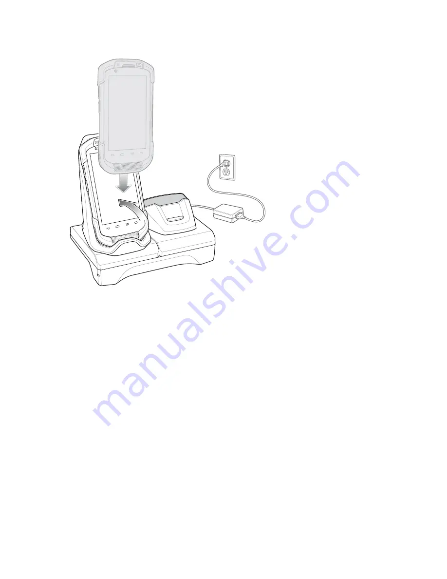
Figure 102: Battery Charging

2

Rotate the top of the device until the connector on the back of the device mates with the connector on the cradle.

3

Ensure the device is connected properly. The charging Charging/Notification LED on the device begins blinking
amber indicating that the device is charging.

Charging the Spare Battery

Procedure:

1

Insert the battery into the right slot to begin charging.

Accessories | 

123

Summary of Contents for Symbol TC70

Page 1: ...TC70 USER GUIDE ...

Page 2: ......

Page 3: ...ten permission Furthermore the purchase of our products shall not be deemed to grant either directly or by implication estoppel or otherwise any license under the copyrights patents or patent applications except for the normal non exclusive royalty free license to use that arises by operation of law in the sale of a product Disclaimer Please note that certain features facilities and capabilities d...

Page 4: ......

Page 5: ...nges to the original guide are listed below Change Date Description A01 Rev A 10 2014 Initial release A02 Rev A 8 2015 Add support for Google Mobile Services 5 Revision History A02 Rev B 2 2016 Correct bracket part number ...

Page 6: ......

Page 7: ... Account Setup 24 Replacing the Battery 24 Replacing the microSD Card 26 Battery Management 27 Monitor Battery Usage 27 Low Battery Notification 28 Battery Optimization 29 Turning Off the Radios 29 Setting the Date and Time 29 Display Setting 30 Setting the Screen Brightness 30 Setting Screen Rotation 30 Setting Screen Timeout Setting 30 Setting Font Size 31 Setting Touch Key Light 31 Touch Mode 3...

Page 8: ...iUser Logout 55 Resetting the Device 55 Performing a Soft Reset 55 Performing a Hard Reset 55 Suspend Mode 56 Chapter 3 Applications 59 File Browser 59 People 60 Adding People 60 Editing People 60 Deleting People 60 Camera 61 Taking Photos 61 Taking a Panoramic Photo 63 Recording Videos 64 Photo Settings 66 Video Settings 68 Gallery 69 Working with Albums 70 Share an Album 71 Get Album Information...

Page 9: ... Imager Bluetooth HID 96 DataWedge 96 Enabling DataWedge 96 Disabling DataWedge 97 Chapter 5 Wireless 99 Wireless Local Area Networks 99 Scan and Connect to a Wi Fi Network 99 Configuring a Wi Fi Network 101 Manually Adding a Wi Fi Network 103 Configuring for a Proxy Server 103 Configuring the Device to Use a Static IP Address 104 Advanced Wi Fi Settings 105 Remove a Wi Fi Network 107 Bluetooth 10...

Page 10: ...ripe Reader 134 Attaching the MSR 134 Removing the MSR 135 Reading Magnetic Stripe Cards 136 2 5 mm Audio Adapter 137 Attaching the 2 5 mm Audio Adapter 137 Connecting a Headset to the Audio Adapter 138 Device with Audio Adapter in Holster 139 Removing the 2 5 mm Audio Adapter 140 3 5 mm Audio Adapter 140 Attaching the 3 5 mm Audio Adapter 141 Connecting a Headset to the 3 5 mm Audio Adapter 141 D...

Page 11: ...153 Chapter 7 Maintenance and Troubleshooting 155 Maintaining the TC70 155 Battery Safety Guidelines 155 Cleaning Instructions 156 Cleaning the TC70 157 Connector Cleaning 157 Cleaning Cradle Connectors 157 Troubleshooting 158 TC70 158 Chapter 8 Technical Specifications 161 TC70 161 Contents 11 ...

Page 12: ...12 Contents ...

Page 13: ...e Serv ices GMS WLAN 802 11 a b g n d h i k r WPAN Blue tooth v4 0 Low Energy 4 7 High Defini tion 1280 x 720 LCD 1 GB RAM 8 GB Flash SLC High Reliability Flash 2D imager and integrated NFC Android based Android Open Source Project 4 4 2 TC70 Standard with GMS WLAN 802 11 a b g n d h i k r WPAN Blue tooth v4 0 Low Energy 4 7 High Defini tion 1280 x 720 LCD 1 GB RAM 8 GB Flash SLC High Reliability ...

Page 14: ...ndow and screen names Drop down list and list box names Check box and radio button names Button names on a screen Bullets indicate Action items Lists of alternatives Lists of required steps that are not necessarily sequential Sequential lists for example lists that describe step by step procedures appear as numbered lists Icon Conventions The documentation set is designed to give the reader more v...

Page 15: ...product name found on manufacturing label Software type and version number Figure 1 Manufacturing Label Customer Support responds to calls by email or telephone within the time limits set forth in support agreements If the problem cannot be solved by Customer Support the user may need to return the equipment for servicing and will be given specific directions We are not responsible for any damages...

Page 16: ......

Page 17: ...orage and shipping 2 Verify that the following were received TC70 mobile computer 4 620 mAh Lithium ion battery Hand strap Regulatory Guide Quick Start Guide 3 Inspect the equipment for damage If any equipment is missing or damaged contact the Global Customer Support center immediately 4 Prior to using the TC70 for the first time remove the protective shipping film that covers the scan window disp...

Page 18: ...Back Button Displays the previous screen 5 Home Button Displays the Home screen with a single press Displays recently used ap plications when held for a short period of time On TC70 with GMS opens the Google Now screen when held for a short period of time 6 Microphone Use for communications in Handset mode 7 Charging Contacts Provides power to the device from cables and cradles 8 Speaker Provides ...

Page 19: ... communications in Speakerphone mode 15 Receiver Use for audio playback in Handset mode 16 Charging Notifica tion LED Indicates battery charging status while charging and application generated notifications 17 Data Capture LED Indicates data capture status 18 Front Facing Cam era Use to take photos and videos Figure 3 TC70 Rear View 26 25 23 22 20 19 29 28 27 21 24 23 Table 2 Back View Features Nu...

Page 20: ...e Procedure 1 Install a micro secure digital SD card optional 2 Install hand strap optional 3 Install the battery 4 Charge the TC70 5 Power on the TC70 Installing a microSD Card The microSD card slot provides secondary non volatile storage The slot is located under the battery pack Refer to the documentation provided with the card for more information and follow the manufacturer s recommendations ...

Page 21: ...he hand strap is optional Skip this section if not installing the hand strap Procedure 1 Remove the hand strap filler from the hand strap slot Store the hand strap filler in a safe place for future replacement Figure 5 Remove Filler 2 Insert the hand strap plate into the hand strap slot Figure 6 Insert Hand Strap 3 Insert the battery bottom first into the battery compartment in the back of the TC7...

Page 22: ...ry compartment until the battery release latches snap into place Figure 8 Press Down on Battery 6 Place hand strap clip into hand strap mounting slot and pull down until it snaps into place Figure 9 Secure Hand Strap Clip Installing the Battery Procedure 1 Insert the battery bottom first into the battery compartment in the back of the TC70 22 Getting Started ...

Page 23: ...e 5 Slot Charge Only Cradle 5 Slot Ethernet Cradle The 4 620 mAh battery fully charges in approximately six hours at room temperature Charge batteries in temperatures from 0 C to 40 C 32 F to 104 F The TC70 or accessory always performs battery charging in a safe and intelligent manner At higher temperatures e g approximately 37 C 98 F the TC70 or accessory may for small periods of time alternately...

Page 24: ...harging error but the battery is at end of useful life e g Temperature is too low or too high Charging has gone on too long without completion typically eight hours Google Account Setup Note The TC70 has to be connected to the internet through Wi Fi in order to set up a Google account The first time the TC70 starts the Setup Wizard displays Follow the on screen instructions to set up a Google acco...

Page 25: ...Figure 12 Remove Hand Strap Clip 5 Press the two battery latches in Figure 13 Press Battery Latches 6 Lift the battery from the TC70 Getting Started 25 ...

Page 26: ...into place 9 Replace the hand strap if required 10 Press and hold the Power button to turn on the TC70 Replacing the microSD Card Procedure 1 Press the Power button until the menu appears 2 Touch Power off 3 If hand strap is attached slide the hand strap clip up toward the top of the TC70 and then lift Figure 15 Remove Hand Strap Clip 4 Press the two battery latches in 26 Getting Started ...

Page 27: ...and strap if required 14 Press and hold the Power button to turn on the TC70 Battery Management Note Prior to checking the battery charge level remove the TC70 from any AC power source cradle or cable To check the charge status of the main battery on the Home screen touch About phone Battery Management Battery status indicates that the battery is discharging and Battery level lists the battery cha...

Page 28: ... display different information Some applications include buttons that open screens with settings to adjust power use Low Battery Notification When the battery charge level drops below 18 the TC70 displays a notice to connect the TC70 to power The user should charge the battery using one of the charging accessories Figure 19 Low Battery Notification When the battery charge drops below 10 the TC70 d...

Page 29: ... the Radios Procedure 1 Press the Power button until the menu appears 2 Touch Airplane mode The airplane icon appears in the Status bar indicating that all the radios are off Setting the Date and Time The user is only required to set the time zone or set the date and time when the wireless LAN does not support Newtwork Time Protocol NTP Procedure 1 On the Home screen touch 2 Touch 3 Touch Date tim...

Page 30: ...he brightness using the built in light sensor Deselect Auto to set the brightness manually Use the slider to set a brightness level 6 Touch Setting Screen Rotation By default screen rotation is disabled To enable screen rotation Procedure 1 On the Home screen touch 2 Touch 3 Touch Display 4 Check Auto rotate screen to set the TC70 to automatically switch orientation when the TC70 is rotated Note T...

Page 31: ...ch key light to save battery power Procedure 1 Touch 2 Touch 3 Touch Display 4 Touch Touch key light 5 Select one of the options Always off The touch key light is off 6 seconds The touch key light stays on for six seconds and then turns off default 10 seconds The touch key light stays on for 10 seconds and then turns off 15 seconds The touch key light stays on for 15 seconds and then turns off 30 ...

Page 32: ...e can be made of medical latex leather cotton or wool For optimal performance use Zebra certified stylus Procedure 1 Touch 2 Touch 3 Touch Display 4 Touch Touch Mode Figure 22 Touch Mode Dialog Box 5 Touch Stylus and Finger to use a finger or a stylus on the screen or touch Glove and Finger to use a finger or a gloved finger on the screen 6 Touch 32 Getting Started ...

Page 33: ...ion setting Procedure 1 On the Home screen touch 2 Touch 3 Touch Display 4 Touch Pulse notification light to toggle the notification on or off 5 Touch General Sound Setting Use the Sounds settings to configure media and alarm volumes On the Home screen touch Sounds Alternately touch the Status bar and drag down to open the Notification panel Touch Sounds Figure 23 Sounds Screen Volumes Use to chan...

Page 34: ...k volume Controls the scan good decode beep volume Bottom row icons Places all sounds except media and alarms in silence mode Places all sounds except media and alarms in vibrate mode Places all sounds in sound mode Audio profile Touch to set audio profile On the Audio profile screen touch Audio profile Figure 25 Audio Profile Dialog Box 34 Getting Started ...

Page 35: ...ouched default enabled Touch sounds Check to play a sound when making screen selections default enabled Screen lock sounds Check to play a sound when locking and unlocking the screen default disabled Vibrate on touch Check to have the device vibrate when touching soft keys and on certain screen interactions default enabled Wake Up Sources By default the TC70 wakes from suspend mode when the user p...

Page 36: ...Figure 26 Wake Up Sources Dialog Box 4 Touch 36 Getting Started ...

Page 37: ... To enable go to Settings Accessibility Network Location Provider Adds a location provider which uses mobile network tower information and Wi Fi access point information to provide a location without using GPS To enable go to Settings Location access Widevine DRM Enables the digital rights management so that protected content can be played Enable via DRM Info from the Play Store Google Cloud Messa...

Page 38: ...us icons right side and notification icons left side For more information see Status Icons on page 39 and Manag ing Notifications on page 41 2 Browser Icons Opens browser application 3 All Apps Icon Opens the APPS window 4 Shortcut Icons Opens applications installed on the TC70 See Application Shortcuts and Widgets on page 42 for more information 5 Widgets Launches stand alone applications that ru...

Page 39: ...cations exist Open the Notifications panel to view all notifications and status Status Icons Table 6 Status Icons Icon Description Indicates that the Alarm is active Indicates that all sounds except media and alarms are silenced and vibrate mode is active Indicates that all sounds except media and alarms are silenced Indicates that the battery is fully charged Indicates that the battery is partial...

Page 40: ...es that the TC70 is downloading data when animated and download is complete when stat ic Indicates that the TC70 is connected via USB cable Indicates that the TC70 is connected to or disconnected from virtual private network VPN Preparing SD card Indicates that USB debugging is enabled on the TC70 Indicates that the MultiUser feature is enabled Appears only when MultiUser Administrator ap plicatio...

Page 41: ...ion panel drag the Status bar down from the top of the screen Figure 29 Notification Panel To respond to a notification open the Notifications Panel and then touch a notification The Notifications Panel closes and the subsequent activity is dependent on the notification To clear all notifications open the Notifications Panel and then touch All event based notifications are removed Ongoing notifica...

Page 42: ...ouch to opens the Battery screen Airplane Mode Displays the Airplane mode status Touch to toggle Airplane mode on and off Turn on Airplane mode to turn off all the radios Bluetooth Displays the current state of the Bluetooth radio Touch to open the Bluetooth settings screen Location Displays the current state of the Location settings Touch to opens the Location settings screen To close the Quick S...

Page 43: ...Removing an App or Widget from the Home Screen Procedure 1 Go to the desired Home screen 2 Touch and hold the application shortcut or widget icon until it floats on the screen 3 Drag the icon to on the top of the screen and then release Folders Use Folders to organize similar applications together Tap the folder to open and display items in the folder Creating a Folder To create a folder there mus...

Page 44: ... animated wallpaper image Wallpapers Select to use a wallpaper image 4 Touch Save or Set wallpaper Using the Touchscreen Use the multi tap sensitive screen to operate the device Tap Tap to select items on the screen type letters and symbols using the on screen keyboard press on screen buttons Tap and Hold Tap and hold an item on the Home screen to move it to a new location or to the trash an item ...

Page 45: ...ne of the top row keys until a menu appears then select a number Keys with alternate characters display an ellipsis below the character Touch and hold the Shift key with one finger touch one or more capital letters or symbols to enter them and then lift both fingers to return to the lowercase keyboard Touch to switch to the numbers and symbols keyboard Touch the key on the numbers and symbols keyb...

Page 46: ... only Clock Use to schedule alarms for appointments or as a wake up DataWedge Enables data capture using the imager Downloads lists all downloads files Drive Upload photos videos documents and other files to personal storage site TC70 Pro fessional with GMS only DWDemo Provides a way to demonstrate the data capture features using the imager See DataWedge Demonstration on page 77 for more informati...

Page 47: ...rch for any business or place of interest Provides turn by turn navigation with voice guid ance and traffic avoidance and alternate routes for drivers cyclist walkers and users of public transportation TC70 Standard with GMS only MLog Manager Use to capture log files for diagnostics See MLog Manager on page 82 for more information MobiControl Stage Opens the MobiControl Stage application to stage ...

Page 48: ...S only Play Newsstand Displays current news TC70 Standard with GMS only Play Store Download music movies books and Android apps and games from the Google Play Store TC70 Standard with GMS only PTT Express Use to launch PTT Express client for VoIP communication Rapid Deployment Allows the TC70 to stage a device for initial use by initiating the deploy ment of settings firmware and software Requires...

Page 49: ... YouTube Use to view videos on the YouTube web site TC70 Standard with GMS only AppLock Administrator Use to configure the Application Lock feature This icon appears after the optional application is installed MultiUser Administrator Use to configure the MultiUser feature This icon appears after the optional application is installed Secure Storage Administrator Use to configure the Secure Storage ...

Page 50: ...open the application Note See Application Shortcuts and Widgets on page 42 for information on creating a shortcut on the Home screen Switching Between Recent Applications Procedure 1 Touch and hold non GMS devices or GMS devices A window appears on the screen with icons of recently used applications 50 Using the TC70 ...

Page 51: ...ng up the locking feature The Locking feature functions differently in Single User mode or Multiple User mode Single User Mode When locked a pattern PIN or password is required to unlock the device Press the Power button to lock the screen The device also locks after a pre defined time out Press and release the Power button to wake the device The Lock screen displays Slide to the right toward to u...

Page 52: ...Figure 35 Lock Screen Figure 36 PIN Screen 52 Using the TC70 ...

Page 53: ...Figure 37 Pattern Screen Using the TC70 53 ...

Page 54: ...og on to the device with each user having access to various applications and features When enabled the Login screen appears after powering on resetting or after the device wakes from suspend mode MultiUser Login Procedure 1 In the Login text field enter the username 54 Using the TC70 ...

Page 55: ...tive 3 Touch Logout 4 The Login screen appears Resetting the Device There are two reset functions soft reset and hard reset Performing a Soft Reset Perform a soft reset if applications stop responding Procedure 1 Press and hold the Power button until the menu appears 2 Touch Reset 3 The device reboots Performing a Hard Reset Caution Performing a hard reset with a SD card installed in the TC70 may ...

Page 56: ...iod of inactivity set in the Display settings window To wake the TC70 from Suspend mode press the Power button The Lock screen displays Slide to the right toward to unlock the screen If the Pattern screen unlock feature is enabled the Pattern screen appears instead of the Lock screen See Un Locking the Screen on page 51 Note If the user enters the PIN password or pattern incorrectly five times the...

Page 57: ...Figure 41 Lock Screen Using the TC70 57 ...

Page 58: ......

Page 59: ...n File Browser touch Figure 42 File Browser Screen The address bar 1 indicates the current folder path Touch the current folder path to manually enter a path and folder name Use 2 to select multiple files folder Use 3 to view the internal storage root folder Use 4 to view the microSD card root folder Use 5 to view the previous folder or to exit the application 59 Applications ...

Page 60: ...to scroll through the lists Adding People Procedure 1 In the People application touch 2 If there are more than one account with contacts touch the one to use 3 Type the contact s name and other information Touch a field to start typing and swipe down to view all categories 4 To add more than one entry for a category for example to add a work address after typing a personal address touch Add new fo...

Page 61: ...rd If a microSD card is not installed the TC70 saves photos and videos on the internal storage Figure 43 Camera Photo Screen 1 Camera Options Touch to select Camera Video or Panorama mode 2 Shutter button Touch to take a photo a panoramic photo or to record a video 3 Photo Settings Touch to select camera settings Taking Photos Note Camera settings are described in Photo Settings on page 66 Procedu...

Page 62: ...options icon and touch 4 To switch between the rear camera and front camera touch and then or 5 Frame the subject on the screen 6 To zoom in or out press two fingers on the display and pinch or expand fingers The zoom controls appear on the screen 62 Applications ...

Page 63: ... takes a photo and a shutter sound plays Alternately touch and hold to focus first before taking a photo then release to take a focused photo The photo momentarily displays as a thumbnail in the upper right corner Taking a Panoramic Photo Panorama mode lets the user create a single wide image by panning slowly across a scene Procedure 1 Touch 2 Touch Applications 63 ...

Page 64: ...area to capture A small white square appears inside the button indicating the capture is in progress If panning too quickly the message Too fast appears 6 Touch to end the shot The panorama appears immediately and a progress indicator displays while it saves the image Recording Videos To record a video Procedure 1 Touch 2 Touch 64 Applications ...

Page 65: ...touch 4 To switch between the rear camera and front camera touch and then or 5 Point the camera and frame the scene 6 To zoom in or out press two fingers on the display and pinch or expand fingers The zoom controls appear on the screen Applications 65 ...

Page 66: ...rner Photo Settings When in Photo mode photo settings are displayed on screen Touch to display the photo settings options Rear Camera Touch to display the photo setting options Figure 49 Rear Photo Setting Options HDR Touch to enable High Dynamic Range HDR imaging HDR adds more dynamic range to photographs the ratio of light to dark HDR uses three photos taken at different exposures to create the ...

Page 67: ...ct auto exposure setting Options Frame Average default Center Weighted or Spot Metering Third Anti Banding Options Off default 50 Hz 60 Hz or Auto Select ISO Set how sensitive the camera is to light Options Auto default ISO Auto HJR ISO100 ISO200 ISO400 ISO800 or ISO1600 Exposure Touch to adjust the exposure settings Options 2 1 0 default 1 or 2 White balance Touch to select how Camera adjusts col...

Page 68: ...e face detection default enabled Touch to switch to the rear camera Video Settings When in Video mode video settings are displayed on screen Touch to display the video settings options Rear Camera Touch to display the photo setting options Figure 51 Rear Video Setting Options Fisrt Time lapse Touch to select a time interval to set the frame rate for time lapse photography Options Off default Slide...

Page 69: ...tch to ON and then set time interval Video quality Touch to select video quality HD 720p High definition 720p default SD 480p Standard definition 480p Video duration Options 30 seconds MMS or 30 minutes default Touch to switch to the rear camera Gallery Note The device supports the following image formats jpeg gif png and bmp The device supports the following video formats H 263 H 264 and MPEG4 Si...

Page 70: ...gical order Touch a photo or video in an album to view it Touch to return to the main Gallery screen Working with Albums Albums are groups of images and videos in folders Touch an album to open it The photos and videos are listed in a chronologically ordered grid The name of the album displays at the top of the screen 70 Applications ...

Page 71: ... Touch and hold an album until it highlights 4 Touch other albums as required 5 Touch The Share menu opens Touch the application to use to share the selected albums 6 Follow the instructions within the selected application Get Album Information Procedure 1 Touch 2 Touch 3 Touch and hold an album until it highlights Applications 71 ...

Page 72: ...ther albums to delete Ensure that other albums are selected 5 Touch Delete 6 In the Delete selected item menu touch OK to delete the album Working with Photos Use Gallery to view photos on the microSD card and edit and share photos Viewing and Browsing Photos To view a photo Procedure 1 Touch 2 Touch 3 Touch an album to open it 4 Touch a photo 72 Applications ...

Page 73: ...in or pinch two fingers together or spread them apart to zoom in or out 9 Drag the photo to view parts that are not in view Cropping a Photo Procedure 1 In Gallery touch a photo to view the controls 2 Touch 3 Touch Crop The cropping tool appears 4 Use the cropping tool to select the portion of the photo to crop Drag from the inside of the cropping tool to move it Drag an edge of the cropping tool ...

Page 74: ...to as a Contact Icon Procedure 1 Touch 2 Touch 3 Touch an album to open it 4 Touch the photo to open it 5 Touch 6 Touch Set picture as 7 Touch Contact photo 8 In the People application touch a contact 9 Touch the blue box and crop the photo accordingly 10 Touch OK Share a Photo Procedure 1 Touch 2 Touch 74 Applications ...

Page 75: ...th the photo attached to a new message Deleting a Photo Procedure 1 Touch 2 Touch 3 Touch an album to open it 4 Touch a photo to open it 5 Touch 6 Touch Delete 7 Touch OK to delete the photo Working with Videos Use Gallery to view videos and share videos Watching Videos Procedure 1 Touch 2 Touch 3 Touch an album to open it 4 Touch a video Applications 75 ...

Page 76: ...haring a Video Procedure 1 Touch 2 Touch 3 Touch an album to open it 4 Touch a video to open it 5 Touch The Share menu appears 6 Touch the application to use to share the selected video The application selected opens with the video attached to a new message Deleting a Video Procedure 1 Touch 76 Applications ...

Page 77: ...on to demonstrate data capture functionality Figure 58 DataWedge Demonstration Window Table 9 DataWedge Demonstration Icons Icon Description Not applicable Indicates that the data capture function is through the imager Toggles between normal scan mode and picklist mode when using the imager to capture bar code data Table continued Applications 77 ...

Page 78: ...ecorder Use Sound Recorder to record audio messages Recordings are saved on the microSD card if installed or the Internal Storage and available in the Music application playlist titled My Recordings Figure 59 Sound Recorder Application PTT Express Voice Client Note PTT Express Voice Client creates Push To Talk PTT communication capability between disparate enterprise devices Leveraging existing Wi...

Page 79: ...communicating on the same talkgroup Plays after the maximum allowed talk time is reached 60 seconds Network Tone Three increasing pitch beeps Plays when PTT Express has acquired the WLAN connection and the service is enabled Three decreasing pitch beeps Plays when PTT Express has lost the WLAN connection or the service is disabled Figure 60 PTT Express Default User Interface Table 10 PTT Express D...

Page 80: ...d by the number next to the icon Indicates that PTT Express Voice client is enabled connected to a WLAN and in a private response Indicates that PTT Express Voice client is enabled and muted Indicates that the PTT Express Voice client is enabled but it is not able to communicate due to a VoIP telephony call is in progress Enabling PTT Communication Procedure 1 Touch 2 Touch 3 Slide the Enable Disa...

Page 81: ...o be initiated using the headset Talk button Figure 61 PTT Buttons 1 1 PTT Button Figure 62 Wired Headset 1 1 Talk Button Creating a Group Call Procedure 1 Press and hold the PTT button or the Talk button on the headset and listen for the talk tone to play If a busy tone is heard release the button and wait a moment before making another attempt Ensure that PTT Express and the WLAN are enabled App...

Page 82: ...to allow others to make calls 3 Release the button when finished talking Disabling PTT Express Voice Client Communication Procedure 1 Touch 2 Touch 3 Slide the Enable Diable Switch to the OFF position The button changes to OFF 4 Touch MLog Manager Use MLog Manager to capture log files for diagnostics See the TC70 Integrator Guide for detailed information on configuring the application Figure 63 ML...

Page 83: ... and then testing on the device Figure 64 SimulScan Demo Home Screen Exporting Sample Forms In order to perform the Postal Transportation Logistics or Manufacturing demonstrations print the example forms stored on the device Procedure 1 Launch SimulScan Demo application 2 On the SimulScan Demo home screen touch HOW TO USE THIS DEMO 3 Scroll down and touch Export sample forms button The device copi...

Page 84: ...n 4 Touch Postal Transportation Logistics 5 Touch Start SimulScan 6 Use the image control at the bottom of the screen to control the flash audio and zoom level Figure 66 Image Controls 7 Position the camera over the form Ensure that the complete border of the form is visible on the screen 8 Hold the device steady 9 Once the device detects the form Tap Screen to Scan appears on the screen 84 Applic...

Page 85: ...o many errors touch Rescan to perform the capture again 12 Touch Accept to confirm the data is correct The Results summary screen appears 13 Touch OK Manufacturing Example The Postal Transportation and Logistics example uses the following form Figure 68 Manufacturing Form Procedure 1 Copy the sample form from the device to a computer See 2 Print this form 3 Place the form on a flat surface Applica...

Page 86: ...1 Touch the text boxes to correct any errors If there are too many errors touch Rescan to perform the capture again 12 Touch Accept to confirm the data is correct The Results summary screen appears 13 Touch OK Settings To set the settings for the SimulScan Demo application touch Menu icon Settings Figure 70 Settings Screen Volume Toggle switch to turn audible notification on and off Haptic Toggle ...

Page 87: ...Icon color text box enter the hex color value for Menu icon and button text 10 In the Key Features text box enter text that will appear under the Key Feature heading This text appears in bullet format 11 Touch one of the SimulScan Document Capture Template fields to select a template a Browse external storage select a template loaded on the device b Default templates select one of the default temp...

Page 88: ...ger Elemez Note Elemez collects specific device information in the background and sends this information to us to help improve product functionality This feature can be disabled See Disabling Elemez Data Collection on page 89 Ensure that the date time and time zone are set correctly prior to using Elemez Use Elemez to provide diagnostics information to Zebra Touch Submit Diagnostics button to send...

Page 89: ...install updates dialog box touch OK 7 Touch OK 8 After uninstall is complete touch OK 9 In the All tab scroll through the list and touch Elemez 10 Touch Disable 11 In the Disable built in app dialog box touch OK 12 Touch Enabling Elemez Data Collection The user can re enable the Elemez application for collection specific data in the background and sending it to Zebra Technologies Procedure 1 From ...

Page 90: ...8 Touch or 9 Touch Enable Elemez 90 Applications ...

Page 91: ...f the art software decoding algorithms to extract the bar code data from the image Operational Modes The TC70 with an integrated imager supports two modes of operation listed below Activate each mode by pressing the Scan button Decode Mode In this mode the TC70 attempts to locate and decode enabled bar codes within its field of view The imager remains in this mode as long as the user holds the sca...

Page 92: ...o the scanner from the bar code this specular reflection can blind the scanner To avoid this scan the bar code so that the beam does not bounce directly back But don t scan at too sharp an angle the scanner needs to collect scattered reflections from the scan to make a successful decode Practice quickly shows what tolerances to work within Hold the TC70 farther away for larger symbols Move the TC7...

Page 93: ...touches the bar code Ensure the bar code is within the area formed by the crosshairs in the aiming pattern The aiming dot is used for increased visibility in bright lighting conditions Figure 76 Aiming Pattern Figure 77 Pick List Mode with Multiple Bar Codes in Aiming Pattern 5 The Data Capture LED lights green and a beep sounds by default to indicate the bar code was decoded successfully 6 Releas...

Page 94: ...ld is in focus text cursor in text field 2 Point the RS507 at a bar code Figure 78 Bar Code Scanning with RS507 3 Press and hold the trigger The red laser aiming pattern turns on to assist in aiming Ensure the bar code is within the area formed by the cross hairs in the aiming pattern The aiming dot is used for increased visibility in bright lighting conditions The RS507 LEDs light green a beep so...

Page 95: ... devices are within 10 meters 32 8 feet of one another 2 Install the battery into the RS507 3 On the TC70 touch 4 Touch Figure 81 Bluetooth Pairing Utility 5 Using the RS507 scan the bar code on the screen The RS507 emits a high low high low beeps The Scan LED flashes green indicating that the RS507 is attempting to establish connection with the TC70 When connection is established the Scan LED tur...

Page 96: ... HID Bar Code 5 Remove the battery from the RS507 6 Re install the battery into the RS507 7 On the TC70 touch 8 Touch 9 Touch Bluetooth 10 Touch SCAN FOR DEVICES The device begins searching for discoverable Bluetooth devices in the area and displays them under AVAILABLE DEVICES 11 Scroll through the list and select RS507 The device connects to the RS507 and Connected appears below the device name ...

Page 97: ... in the checkbox indicating that DataWedge is enabled 6 Touch Disabling DataWedge Procedure 1 Touch 2 Touch 3 Touch 4 Touch Settings 5 Touch the DataWedge enabled checkbox The blue checkmark disappears from the checkbox indicating that DataWedge is disabled 6 Touch Data Capture 97 ...

Page 98: ......

Page 99: ... the infrastructure access points APs access ports switches Radius servers etc for instructions on how to set up the infrastructure Once the infrastructure is set up to enforce the chosen WLAN security scheme use the Wireless networks settings configure the TC70 to match the security scheme The TC70 supports the following WLAN security options Open Wireless Equivalent Privacy WEP Wi Fi Protected A...

Page 100: ...Figure 83 Settings Screen 3 Slide the Wi Fi switch to the ON position 4 Touch Wi Fi The TC70 searches for WLANs in the area and lists them 100 Wireless ...

Page 101: ... configure the TC70 with a fixed internet protocol IP address See Configuring the Device to Use a Static IP Address on page 104 7 In the Wi Fi setting field Connected appears indicating that the TC70 is connected to the WLAN Configuring a Wi Fi Network To set up a Wi Fi network Procedure 1 Touch 2 Touch 3 Touch Wi Fi 4 Slide the switch to the ON position 5 The device searches for WLANs in the area...

Page 102: ...equired touch User certificate and select a user certificate Note User certificates are installed using the Location security settings If required in the Identity text box enter the username credentials If desired in the Anonymous identity text box enter an anonymous identity username If required in the Password text box enter the password for then given identity 10 Note By default the network Pro...

Page 103: ...y 10 Note By default the network Proxy is set to None and the IP settings is set to DHCP See Configuring for a Proxy Server on page 103 for setting connection to a proxy server and see Configuring the Device to Use a Static IP Address on page 104 for setting the device to use a static IP address Touch Save To connect to the saved network touch and hold on the saved network and select Connect to ne...

Page 104: ...roxy for text box enter addresses for web sites that do not require to go through the proxy server Use a comma between addresses 7 Touch Connect 8 Touch Configuring the Device to Use a Static IP Address By default the device is configured to use Dynamic Host Configuration Protocol DHCP to assign an Internet protocol IP address when connecting to a wireless network To configure the device to connec...

Page 105: ...ng sleep Opens a menu to set whether and when the Wi Fi radio turns off Always On The radio stays on when the device enters suspend mode default Only when plugged in The radio stays on while the device is connected to external power Never On The radio turns off when the device enters suspend mode Install Certificates Touch to install certificates Wi Fi optimization Touch to minimize battery usage ...

Page 106: ...ture Wi Fi log files Fusion Logger Touch to open the Fusion Logger application This application maintains a history of high level WLAN events which helps to understand the status of connectivity Figure 88 Fusion Logger Screen Fusion Status Touch to display live status of WLAN state Also provides information of device and connected profile Figure 89 Fusion Status Screen About Version Displays the c...

Page 107: ...no AFH when connecting and discovering devices Avoid making Bluetooth connections and discoveries during critical 802 11b communications AFH for Bluetooth consists of four main sections Channel Classification A method of detecting an interference on a channel by channel basis or pre defined channel mask Link Management Coordinates and distributes the AFH information to the rest of the Bluetooth ne...

Page 108: ... serial cable connection between two Bluetooth peer devices For example connecting the device to a printer Object Push Profile OPP Allows the device to push and pull objects to and from a push server Advanced Audio Distribution Profile A2DP Allows the device to stream stereo quality audio to a wireless headset or wireless stereo speakers Audio Video Remote Control Profile AVRCP Allows the device t...

Page 109: ...uch 3 Slide the Bluetooth switch to the OFF position 4 Touch Discovering Bluetooth Device s The TC70 can receive information from discovered devices without pairing However once paired the TC70 and a paired device exchange information automatically when the Bluetooth radio is on To find Bluetooth devices in the area Procedure 1 Ensure that Bluetooth is enabled on both devices 2 Ensure that the Blu...

Page 110: ...devices list and a trusted paired connection is established Changing the Bluetooth Name By default the TC70 has a generic Bluetooth name that is visible to other devices when connected Procedure 1 Touch 2 Touch 3 Touch Bluetooth 4 If Bluetooth is not on slide the switch to the ON position 5 Touch 6 Touch Rename device 7 Enter a name and touch Done 8 Touch Connecting to a Bluetooth Device Once pair...

Page 111: ...ice and erase all pairing information Procedure 1 Touch 2 Touch 3 Touch Bluetooth 4 In the PAIRED DEVICES list touch next to the device name 5 Touch Unpair 6 Touch Near Field Communications NFC HF RFID is a short range wireless connectivity technology standard that enables secure transaction between a reader and a contactless smartcard The technology is based on ISO IEC 14443 type A and B proximit...

Page 112: ... Reading Cards 3 Move TC70 close to the NFC card until the TC70 detects the card 4 Hold the card steadily until the transaction is complete usually indicated by the application Sharing Information Using NFC You can beam content like a web page contact cards pictures YouTube links or location information from your screen to another device by bringing the devices together back to back Prerequisites ...

Page 113: ...size the message Touch to beam appears 3 Touch anywhere on the screen The transfer begins Enterprise NFC Settings The Enterprise NFC Settings provides advanced configuration of the NFC radio To configure the NFC settings touch Settings More Enterprise NFC Settings Figure 94 Wireless Networks Screen Wireless 113 ...

Page 114: ...d Card Emulation Mode Enable or disable card emulation mode Default Disabled Enable CE mode Touch to enable or disable card emulation mode Default Enabled Enable NFC on Lock Screen Enable or disable NFC on lock screen Reset to Default Reset all NFC settings to factory default settings Reader Mode Use the Reader Mode settings to configure the NFC radio 114 Wireless ...

Page 115: ...C transaction performance while reading small amounts data Default Enabled Card Communication speed Touch to set the baud rate for type A and type B cards Options 106 kbps default for Type A 212 kbps 424 kbps or No restrictions default for Type B Data Usage Data usage refers to the amount of data uploaded or downloaded by the device during a given period To monitor data usage go to Data usage Data...

Page 116: ...eriod of time within the data usage cycle This range determines the usage amount displayed just below the graph Drag lines to change the period Below the graph is a list of applications that used data Set Auto Sync You can also conserve data usage by syncing your applications manually only when you need the data rather than relying on auto sync To turn auto sync off or on touch Auto sync data 116 ...

Page 117: ...4 Slot Battery Charger using the Battery Adapter Cup 5 Slot Ethernet Cradle CRD TC7X SE5EU1 01 Provides device charging and provides Ethernet commu nication for up to five devices Use with power supply p n PWRS 14000 241R and DC line cord p n 50 16002 029R Can accommodate one 4 Slot Battery Charger using the Battery Adapter Cup Cradle Mount BRKT SCRD SMRK 01 Mounts the 5 Slot Charge Only Cradle 5 ...

Page 118: ...mium Rugged headset 2 5 mm Quick Disconnect Adapter Cable 25 124387 02R Provides connection to the RCH50 RCH51 headset 3 5 mm Audio Adapter ADP TC7X AUD35 01 Snaps onto the device and provides audio to a wired headset with 3 5 mm plug 3 5 mm Headset HDST 35MM PTVP 01 Use for PTT and VoIP calls 3 5 mm Quick Disconnect Adapter Cable ADP 35M QDCBL1 01 Provides connection to the 3 5 mm Headset Scannin...

Page 119: ...ides power from the power supply to the 5 Slot Charge Only Cradle and 5 Slot Ethernet Cradle 2 Slot Charge Only Cradle The 2 Slot Charge Only Cradle Provides 5 VDC power for operating the device Charges the device s battery Charges a spare battery Figure 98 2 Slot Charge Only Cradle 1 2 1 Power LED Lights green indicating that the cradle is receiving power 2 Spare battery Charging LED Charging the...

Page 120: ...g 2 Ensure the device is seated properly Charging the Spare Battery Procedure 1 Insert the battery into the right slot to begin charging Figure 100 Spare Battery Charging 2 Ensure the battery is seated properly 120 Accessories ...

Page 121: ...arging check placement of spare battery and battery is at the end of useful life Off No spare battery in slot spare battery not placed correct ly cradle is not powered Charging Temperature Charge batteries in temperatures from 0 C to 40 C 32 F to 104 F The device or cradle always performs battery charging in a safe and intelligent manner At higher temperatures e g approximately 37 C 98 F the devic...

Page 122: ...t USB Ethernet Cradle 1 2 1 Power LED Lights green indicating that the cradle is receiving power 2 Spare Battery Charging LED Charging the Device Procedure 1 Place the bottom of the device into the base 122 Accessories ...

Page 123: ...mates with the connector on the cradle 3 Ensure the device is connected properly The charging Charging Notification LED on the device begins blinking amber indicating that the device is charging Charging the Spare Battery Procedure 1 Insert the battery into the right slot to begin charging Accessories 123 ...

Page 124: ...lly charges in less than six hours at room temperature Table 14 Spare Battery Charging LED Indicators LED Indication Slow Blinking Amber Spare battery is charging Solid Green Charging complete Fast Blinking Amber Error in charging check placement of spare battery Slow Blinking Red Spare battery is charging and battery is at the end of use ful life Solid Red Charging complete and battery is at the ...

Page 125: ...ation Ensure that the switch on the USB Ethernet module is set properly Turn the cradle over to view the module Figure 104 2 Slot USB Ethernet Cradle Module Switch For Ethernet communication slide the switch to the position For USB communication slide the switch to the position Place the switch in the center position to disable communications Ethernet LED Indicators There are two LEDs on the USB E...

Page 126: ... 5 Slot Charge Only Cradle The 5 Slot Charge Only Cradle Provides 5 VDC power for operating the TC70 Simultaneously charges up to five TC70s and up to four TC70s and on 4 Slot Battery Charger using the Battery Charger Adapter See the TC70 Integrator Guide for information on installing the 4 Slot Battery Charger onto the cradle Consists of a cradle base and cups that can be configured for various c...

Page 127: ...Charging the TC70 Procedure 1 Insert the TC70 into a slot to begin charging Figure 107 TC70 Battery Charging Accessories 127 ...

Page 128: ...ging in the device The 4 620 mAh battery fully charges in less than six hours at room temperature Spare Battery Charging The Spare battery Charging LED on the cup indicates the status of the spare battery charging The 4 620 mAh battery fully charges in less than six hours at room temperature Table 16 Spare Battery Charging LED Indicators LED Indication Slow Blinking Amber Spare battery is charging...

Page 129: ...imately 37 C 98 F the device or cradle may for small periods of time alternately enable and disable battery charging to keep the battery at acceptable temperatures The device and cradle indicates when charging is disabled due to abnormal temperatures via its LED 5 Slot Ethernet Cradle Caution Ensure that you follow the guidelines for battery safety described in Battery Safety Guidelines on page 15...

Page 130: ...9 5 Slot Ethernet Cradle 1 2 1 1000 LED Indicates 1 Gbps data rate 2 100 10 LED Indicates 100 Mbps or 10 Mbps data rate Charging the TC70 Procedure 1 Insert the TC70 into a slot to begin charging 130 Accessories ...

Page 131: ...Figure 110 TC70 Battery Charging 2 Ensure the TC70 is seated properly Figure 111 5 Slot Ethernet Cradle with 4 Slot Battery Charger Accessories 131 ...

Page 132: ...d Charging complete and battery is at the end of useful life Fast Blinking Red Error in charging check placement of spare battery and battery is at the end of useful life Off No spare battery in slot spare battery not placed correct ly cradle is not powered Charging Temperature Charge batteries in temperatures from 0 C to 40 C 32 F to 104 F The device or cradle always performs battery charging in ...

Page 133: ... 100 10 LED 1 Gbps On Blink Off 100 Mbps Off On Blink 10 Mbps Off On Blink 4 Slot Battery Charger This section describes how to use the 4 Slot Battery Charger to charge up to four TC70 batteries Charging Spare Batteries Procedure 1 Connect the charger to a power source 2 Insert the battery into a battery charging well and gently press down on the battery to ensure proper contact Figure 112 4 Slot ...

Page 134: ...y and battery is at the end of useful life Off No spare battery in slot spare battery not placed correct ly cradle is not powered Charging Temperature Charge batteries in temperatures from 0 C to 40 C 32 F to 104 F The battery charger always performs battery charging in a safe and intelligent manner At higher temperatures e g approximately 37 C 98 F the battery charger may for small periods of tim...

Page 135: ... into position 3 Using a flat end plastic tool slide the lock switch down to lock the MSR Figure 114 Lock MSR Removing the MSR Procedure 1 Using a flat end plastic tool slide the lock switch up to unlock the MSR Figure 115 Unlock MSR 2 Press the two release buttons Accessories 135 ...

Page 136: ...ead magnetic stripe card Procedure 1 Ensure that MSR input is enabled in DataWedge and the cursor is in a text field 2 Grip TC70 firmly in one hand 3 Hold magnetic stripe card firmly in the other hand 4 Align the magnetic stripe on the card away from the display and swipe the card smoothly in either direction 136 Accessories ...

Page 137: ... mm Audio Adapter snaps onto the back of the TC70 and removes easily when not in use When attached to the TC70 the Audio Adapter allows a user to connect a wired headset to the TC70 Attaching the 2 5 mm Audio Adapter Procedure 1 Align the top mounting points on the Audio Adapter with the mounting slots on the TC70 Accessories 137 ...

Page 138: ...r down and press down until it snaps into position Figure 119 Rotate Audio Adapter onto TC70 Connecting a Headset to the Audio Adapter Procedure 1 Lift the rubber plug from the audio jack 2 Insert the headset plug into the jack on the Audio Adapter 138 Accessories ...

Page 139: ...t wire into the wire holder on the Audio Adapter Figure 121 Device with Audio Adapter in Holster When using the TC70 and the audio adapter in a holster ensure that the display faces in and the headset cable is securely attached to the audio adapter Accessories 139 ...

Page 140: ...ottom of the Audio Adapter away from the TC70 Figure 123 Remove Audio Adapter from TC70 3 Remove Audio Adapter from the TC70 3 5 mm Audio Adapter The 3 5 mm Audio Adapter snaps onto the back of the TC70 and removes easily when not in use When attached to the TC70 the 3 55 mm Audio Adapter allows a user to connect a wired headset to the TC70 140 Accessories ...

Page 141: ...n the TC70 Figure 124 Audio Adapter Installation 2 Rotate the Audio Adapter down and press down until it snaps into position Connecting a Headset to the 3 5 mm Audio Adapter Procedure 1 Connect the Quick Disconnect connect of the headset to the Quick Disconnect connector of the 3 5 mm Quick Disconnect Adapter Cable Accessories 141 ...

Page 142: ...dapter Cable to the 3 5 mm Audio Adapter Figure 126 Connect Adapter Cable to Audio Adapter Device with 3 5 mm Audio Adapter in Holster When using the TC70 and the audio adapter in a holster ensure that the display faces in and the headset cable is securely attached to the audio adapter 142 Accessories ...

Page 143: ...dio Adapter in Holster Removing the 3 5 mm Audio Adapter Procedure 1 Disconnect headset plug from 3 5 mm Audio Adapter 2 Lift the bottom of the Audio Adapter away from the TC70 Figure 128 Remove Audio Adapter from TC70 Accessories 143 ...

Page 144: ...data to a host computer and provide power for charging the TC70 Connecting to TC70 Procedure 1 Align the top mounting points on the cable with the mounting slots on the TC70 Figure 129 Cable Installation 2 Rotate the cable down and press until it snaps into place Magnetics hold the cable to the TC70 Figure 130 Cable Attached to TC70 USB Communication Procedure 1 Connect the Snap On USB Cable to th...

Page 145: ...host computer Charging the TC70 Procedure 1 Connect the Snap On USB Cable to the TC70 2 Connect the power supply to the Snap On USB Cable Figure 132 Power Setup 3 Connect to the power supply to an AC outlet Disconnecting from TC70 Procedure 1 Press down on the cable Accessories 145 ...

Page 146: ...in temperatures from 0 C to 40 C 32 F to 104 F The device always performs battery charging in a safe and intelligent manner At higher temperatures e g approximately 37 C 98 F the device may for small periods of time alternately enable and disable battery charging to keep the battery at acceptable temperatures The device indicates when charging is disabled due to abnormal temperatures via its LED C...

Page 147: ...g 2 Ensure the TC70 is seated properly 3 Slide the two yellow locking tabs up to lock the cable to the TC70 Figure 136 Lock Cable Cup 4 Connect the power supply to the Charging Cable Cup and to a power source Accessories 147 ...

Page 148: ... battery charging in a safe and intelligent manner At higher temperatures e g approximately 37 C 98 F the device may for small periods of time alternately enable and disable battery charging to keep the battery at acceptable temperatures The device indicates when charging is disabled due to abnormal temperatures via its LED Snap On DEX Cable The Snap On DEX Cable snaps on to the back of the TC70 a...

Page 149: ...38 Cable Installation 2 Rotate the cable down and press until it snaps into place Magnetics hold the cable to the TC70 Figure 139 Cable Attached to TC70 DEX Communication Procedure 1 Connect the Snap On DEX Cable to the TC70 2 Connect the DEX connector of the cable to a device such as a vending machine Accessories 149 ...

Page 150: ...onnection Disconnecting from TC70 Procedure 1 Press down on the cable Figure 141 Press Down on Cable 2 Rotate away from the TC70 The magnetics release the cable from the TC70 Figure 142 Remove Cable from TC70 150 Accessories ...

Page 151: ...igger Handle Plate Installing the Trigger Handle Plate Procedure 1 Press and hold the Power button until the menu appears 2 Touch Power off 3 Touch OK 4 Press in the two battery latches 5 Lift the battery from the device 6 Remove the hand strap filler plate from the hand strap slot Store the hand strap filler plate in a safe place for future replacement Figure 144 Remove Hand Strap Plate 7 Insert ...

Page 152: ... 10 Press the battery down into the battery compartment until the battery release latches snap into place Inserting the Device into the Trigger Handle Procedure 1 Align the back of the Trigger handle with the Trigger Mounting Plate Figure 146 Connect Device to Trigger Handle 2 Press the two release latches 3 Rotate the device down and press down until it snaps into place 152 Accessories ...

Page 153: ... Device from the Trigger Handle Procedure 1 Press both Trigger Handle release latches Figure 148 Press Release Latches 2 Rotate the device up and remove from the Trigger handle 3 Rotate the device down and press down until it snaps into place Accessories 153 ...

Page 154: ...Figure 149 Rotate Device onto Trigger Handle 154 Accessories ...

Page 155: ...ls Particular care should be taken where the device is charged in a non commercial environment Follow battery usage storage and charging guidelines found in this guide Improper battery use may result in a fire explosion or other hazard To charge the mobile device battery the battery and charger temperatures must be between 32 ºF and 104 ºF 0 ºC and 40 ºC Do not use incompatible batteries and charg...

Page 156: ...ng chemicals are known to damage the plastics on the device and should not come in contact with the device ammonia solutions compounds of amines or ammonia acetone ketones ethers aromatic and chlorinated hydrocarbons acqueous or alcoholic alkaline solutions ethanolamine toluene trichloroethylene benzene carbolic acid and TB lysoform Cleaning Instructions Do not apply liquid directly to the device ...

Page 157: ...e on the connector 4 Repeat at least three times 5 Use the cotton tipped applicator dipped in alcohol to remove any grease and dirt near the connector area 6 Use a dry cotton tipped applicator and repeat steps 4 through 6 Caution Do not point nozzle at yourself and others ensure the nozzle or tube is away from your face 7 Spray compressed air on the connector area by pointing the tube nozzle about...

Page 158: ...e charged Charge or replace the battery in the TC70 Battery did not charge Battery failed Replace battery If the TC70 still does not operate perform a reset TC70 removed from cra dle while battery was charging Insert TC70 in cradle The 4 620 mAh battery fully charges in less than six hours at room temperature Extreme battery tempera ture Battery does not charge if ambient temperature is below 0 C ...

Page 159: ...ng application is not loaded Load a scanning application on the TC70 or enable Data Wedge See the system administrator Unreadable bar code Ensure the symbol is not defaced Distance between exit window and bar code is incorrect Place the TC70 within proper scanning range TC70 is not programmed for the bar code Program the TC70 to accept the type of bar code being scan ned Refer to the EMDK or DataW...

Page 160: ...0 User enters incorrect pass word If the user enters an incorrect password eight times the user is requested to enter a code before trying again If the user forgot the password contact system administrator 160 Maintenance and Troubleshooting ...

Page 161: ...ble Lithium Ion 3 7V 4 620 mAh battery Expansion Slot User accessible 32 GB microSD slot with SDHC and SDXC support Connection Interface Universal Serial Bus USB 2 0 High Speed host and client Notification Audible tone plus multi color LEDs vibration Voice and Audio Three microphone support with noise cancellation vibrate alert speaker Bluetooth wireless headset support Performance Characteristics...

Page 162: ... Data and Voice Com munications Radio IEEE 802 11a b g n d h I Data Rates Supported 5GHz 802 11a n up to 150 Mbps 2 4GHz 802 11b g n up to 72 2 Mbps Operating Channels 5 GHz Chan 36 165 5180 5825 MHz 2 4 GHz Chan 1 11 2412 2462 MHz North America FCC and IC Chan 1 13 2412 2472 MHz Rest of the World Actual operating channels frequencies depend on regulatory rules and certification agency Security Se...

Page 163: ...00 ft candles 107 639 lux Focal Distance From front of engine 17 7 cm 7 0 in Laser Aiming Element Visible Laser Diode VLD 655 nm 10 nm Central Dot Optical Power 0 6 mW typical Pattern Angle 48 0º horizontal 38 0º vertical Illumination System LEDs Warm white LED Pattern Angle 80 at 505 intensity Camera Specifications Resolution Rear 8 Mega pixel auto focus with flash Front 1 3 Mega pixel fixed focu...

Page 164: ......

Page 165: ......

Page 166: ...ebra com Zebra and the stylized Zebra head are trademarks of ZIH Corp registered in many jurisdictions worldwide The Symbol logo is a registered trademark of Symbol Technologies Inc a Zebra Technologies company All other trademarks are the property of their respective owners 2016 Symbol Technologies LLC All rights reserved ...

Reviews: