2 - 8
SE4750 Integration Guide
Window Material
Many window materials that look clear can contain stresses and distortions that reduce performance. For this
reason, use only cell-cast plastics or optical glass (with or without an anti reflection coating, depending on the
application). Following are descriptions of three popular window materials: PMMA, ADC (CR-39
TM
), and
chemically tempered glass.
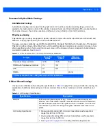
outlines the suggested window properties.
When using plastic materials pay extra attention to the wavefront distortion recommendation specified above.
Colored windows are not recommended because they can significantly degrade performance of the white
illumination system and adversely affect cellphone reading mode.
Cell Cast Acrylic (ASTM: PMMA)
Cell Cast Acrylic, or Poly-methyl Methacrylic (PMMA) is fabricated by casting acrylic between two precision sheets
of glass. This material has very good optical quality, reasonably good impact resistance and low initial cost, but is
relatively soft and susceptible to attack by chemicals, mechanical stresses, and UV light. Therefore polysiloxane
coating is strongly recommended. Acrylic can be laser cut into odd shapes and ultrasonically welded.
Cell Cast ADC (ASTM: ADC)
Also known as CR-39
TM
, Allyl Diglycol Carbonate (ADC) is a thermal-setting plastic produced by cell-casting. Most
plastic eyeglasses sold today are uncoated, cell-cast CR-39. This material has excellent chemical and
environmental resistance, and reasonably good impact resistance. It also has quite good surface hardness, and
therefore does not have to be hard-coated, but may be coated for severe environments. This material cannot be
ultrasonically welded.
Chemically Tempered Glass
Glass is a hard material that provides excellent scratch and abrasion resistance. However, unannealed glass is
brittle. Increasing flexibility strength with minimal optical distortion requires chemical tempering. Glass cannot be
ultrasonically welded and is difficult to cut into odd shapes.
Table 2-1
Suggested Window Properties
Property
Description
Thickness
Typically 0.03 - 0.06 in. (0.7 - 1.5 mm)
Wavefront Distortion (transmission)
0.2 wavelengths peak-to-valley maximum and 0.04
λ
maximum rms over
any 0.08 in. diameter within the clear aperture
Clear Aperture
To extend to within 0.04 in. of the edges all around
Surface Quality
60-20 scratch/dig
Summary of Contents for SE4750
Page 1: ...SE4750 INTEGRATION GUIDE ...
Page 2: ......
Page 3: ...SE4750 INTEGRATION GUIDE 72E 171726 01 Revision A November 2013 ...
Page 6: ...iv SE4750 Integration Guide ...
Page 10: ...viii SE4750 Integration Guide ...
Page 14: ...xii SE4750 Integration Guide ...
Page 18: ...1 4 SE4750 Integration Guide ...
Page 29: ...Installation 2 11 Aiming Pattern Figure 2 6 SE4750 SR LSR AIM Optical Path Aiming Pattern ...
Page 36: ...2 18 SE4750 Integration Guide ...
Page 53: ...Electrical Interface 4 5 Figure 4 3 Parallel Host Flex p n 15 171522 xx ...
Page 66: ...5 12 SE4750 Integration Guide ...
Page 78: ...A 2 SE4750 Integration Guide ...
Page 82: ...Index 4 SE4750 Integration Guide ...
Page 84: ......
Page 85: ......

