background image


MOTOROLA 

SDC1000                       


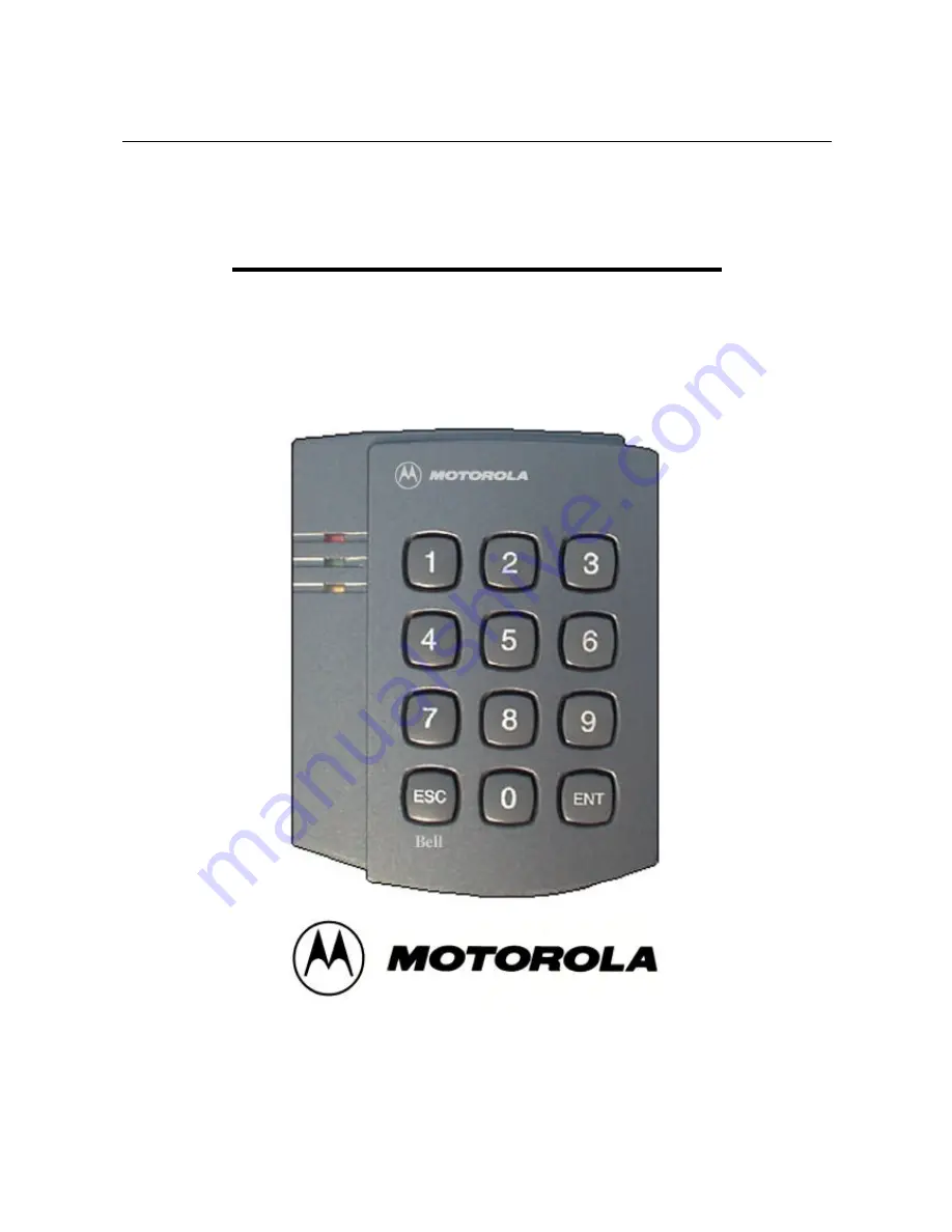
SINGLE DOOR ACCESS CONTROLLER 

1

 -


OPERATING MANUAL 


MOTOROLA SDC1000 


Summary of Contents for SDC1000

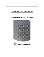
Page 1: ...MOTOROLA SDC1000 SINGLE DOOR ACCESS CONTROLLER 1 OPERATING MANUAL MOTOROLA SDC1000 ...

Page 2: ...neral 3 Features 4 Specifications 5 Name of the Parts 6 Identifying supplied parts 7 Installation of the Product 8 Wire Color Table of the Main Unit 9 Wire Connection in of basic application 10 Initial Setup 11 Operation 12 Setting Changes 13 FCC REGISTRATION INFORMATION 14 Warranty and Service ...

Page 3: ...erating instructions Adjust only those controls that are covered by the operating instructions Improper adjustment of other controls in damage and will often require extensive work by a qualified technician to restore the to normal operation e If the product exhibit a distinct change in performance 2 General SDC1000 is an intelligent one door Access Controller based on powerful 8 bit Microprocesso...

Page 4: ...ax rating at DC 12V 20mA 2 Relay outputs DC12V 2A 1 chime bell output 5V 150mA 1 TTL output 5V 20mA Communication One RS232C port 9600 Baud Rate N 8 1 Keypads 12 Numeric Keypads LED 3 LEDs RED GREEN YELLOW Power DC 12V 200mA Operating Environment 0 C to 60 C 10 to 90 Humidity Reset Power ON Reset 5 Name of each part SDC1000 Main Unit 6 Identifying supplied parts Please unpack and check the content...

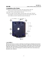
Page 5: ...n unit through the center hole and push the main unit to wall mount to lock the main unit and make sure that the main unit is locked with wall mount CAUTIONS When the main unit is once fixed to wall mount the locking pins will tighten the main unit therefore the operation test of the main unit should be required prior to fix the main unit to wall mount If the main unit has to be disassembled from ...

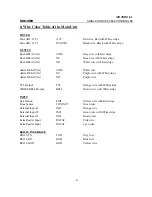
Page 6: ... COM White wire Alarm RELAY 2A NC Purple wire with White stripe Alarm RELAY 2A NO Purple wire TTL Output TTL Orange wire with White stripe CHIME BELL Output BELL Brown wire with White stripe INPUT Exit Button EXIT Yellow wire with Red stripe Door Sensor CONTACT Green wire External Input 1 IN 1 Orange wire External Input 2 IN 2 Green wire with White stripe External Input 3 IN 3 Brown wire Extra Rea...

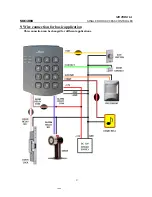
Page 7: ...MOTOROLA SDC1000 SINGLE DOOR ACCESS CONTROLLER 7 9 Wire connection for basic application This connection can be changed for different applications ...

Page 8: ...Power GND wire 9 4 Exit Button connection Connect one of the wire of Exit Button to Exit Button Input Yellow Red stripe wire Connect the other wire of Exit Button to Power GND wire In case of using Normal Closing Contact for Exit Button then please make setting change of ACTIVE level of Exit Button in section 8 20 9 5 Door Contact sensor connection Connect Door Contact sensor COM wire to Door Cont...

Page 9: ...Connector then connect wires as follow Connect RS232 TX Grey wire of Main Unit to pin number 2 of 9 pin connector Connect RS232 RX Blue wire of Main Unit to pin number 3 of 9 pin connector Connect RS232 GND Yellow wire of Main Unit to pin number 5 of 9 pin connector Plug in 9 pin connector to COM1 or COM2 Port of Personal Computer Install and run SDC1000 Time Attendance Software 9 9 Chime Bell Uni...

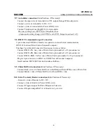
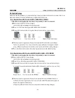
Page 10: ...hen present Master Card again to finish setup Please keep Master Card at the secure location for further setting changes ëNow the Main Unit is entered to normal operation mode with default setting 10 2 Registration of RF Cards with PIN for RF CARD PIN MODE This mode is only applicable when the extra proximity reader is connected çTurn switch on DC12V Power Supply All 3 LEDs will be flashing with s...

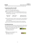
Page 11: ...8 digits PIN number is registered as Master PIN and 4 6 digits PIN followed to Master PIN are registered as User Access PIN numbers then type Master PIN again to finish setup Please write and remember Master PIN number for further setting changes ëNow the Main Unit is entered to normal operation mode with default setting 10 4 Default Setting Values After the Initial Setup the Main Unit stores its ...

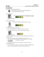
Page 12: ...s Card or PIN is not registered and access is denied then Alarm RELAY activates for 2 sec with sol do sol do melody Unregistered card or PIN If you do not want to activate Alarm then please change settings in section 8 22 11 5 Secure Mode Last exit person can change the mode from Safe Mode to Secure Mode by pressing Secure Code from the keypad so that the Alarm will generate by AUX Inputs Change t...

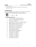
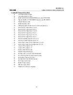
Page 13: ...er Access Cards or PIN 21 Change Door open time when User Access Card or PIN is granted 22 Change Alarm time when User Access Card or PIN is denied 23 Change Alarm time when Try Our error detected 24 Change Alarm time when Door Contact error detected 25 Change Alarm time when AUX 1 Input detected 26 Change Alarm time when AUX 2 Input detected 27 Change Alarm time when AUX 3 Input detected 28 Chang...

Page 14: ...UX 2 Input from H to L 65 Detect AUX 3 Input from L to H 66 Detect AUX 3 Input from H to L 67 Detect Exit Button Input from L to H 68 Detect Exit Button Input from H to L 69 Detect Door Contact sensor Input from L to H 70 Detect Door Contact sensor Input from H to L 71 Activate TTL output to H 72 Activate TTL output to L 77 Enable Chime Bell Output 78 Disable Chime Bell Output 80 Set delay time to...

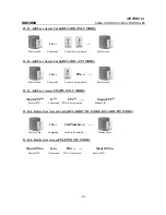
Page 15: ...Cards to be registered Master card 12 13 Add User Access PIN PIN ONLY MODE MasterPINENT 13ENT PINENT MasterPINENT Master PIN Command PIN to be registered Master PIN 12 14 1 Delete User Access Cards RF CARD ONLY MODE RF CARD PIN MODE 14ENT CardNumberENT Master Card Command Cards to be deleted Master Card 12 14 2 Delete User Access PIN PIN ONLY MODE MasterPINENT 14ENT PINENT MasterPINENT Master PIN ...

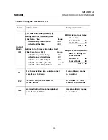
Page 16: ...e Activate only Door Relay 01 Activate only Alarm Relay 02 Activate only TTL Output 04 Activate Door Relay TTL 05 Activate Alarm Relay TTL 06 EX1 Activate Door Relay all the time Door RELAY 01 All the time 50 OM 51 EX2 Activate Alarm Relay and TTL during the Secure mode Alarm TTL 06 Secure Mode 00 OM 06 tt tt is the activating time value seconds from 01sec to 99sec tt value 00sec means no operatio...

Page 17: ...ur error detected Please refer to Table 1 for OM tt 23ENT OMENT ttENT ttENT ttENT Master card or Command Output Mode Door Time Alarm Time TTL Time MasterPINENT 12 24 Change Alarm time when Door Contact error detected Please refer to Table 1 for OM tt 24ENT OMENT ttENT ttENT ttENT Master card or Command Output Mode Door Time Alarm Time TTL Time MasterPINENT 12 25 Change Alarm time when AUX 1 Input ...

Page 18: ...red as default PassWord 12 30 Change Alarm time when Duress Alarm detected Please refer to Table 1 for OM tt 30ENT OMENT ttENT ttENT ttENT Master card or Command Output Mode Door Time Alarm Time TTL Time MasterPINENT 12 31 Test Door open time set by command 21 12 32 Test Alarm time set by command 22 12 33 Test Alarm time set by command 23 12 34 Test Alarm time set by command 24 12 35 Test Alarm ti...

Page 19: ...MasterPINENT 12 43 Enable QUICK ACCESS MODE When QUICK ACCESS MODE is enabled in PIN ONLY MODE Door will open just press ENT key Master card or 43ENT MasterPINENT 12 44 Disable QUICK ACCESS MODE Master card or 44ENT MasterPINENT 12 51 Disable Melody sound Master card or 51ENT MasterPINENT 12 52 Enable Melody sound Master card or 52ENT MasterPINENT 12 60 Change keypad lock time when Try Out error d...

Page 20: ...r card or 64ENT MasterPINENT 12 65 Detect AUX 3 Input from L to H AUX 3 input is detected on the raising edge of AUX 3 input Master card or 65ENT MasterPINENT 12 66 Detect AUX 3 Input from H to L AUX 3 input is detected on the falling edge of AUX 3 input Master card or 66ENT MasterPINENT 12 67 Detect Exit Button Input from L to H Exit Button input is detected on the raising edge of Exit Button inp...

Page 21: ... 12 72 Activate TTL output to L TTL output changes the state from logic 1 to logic 0 when it activates Master card or 72ENT MasterPINENT 12 77 Enable Chime Bell Output Master card or 77ENT MasterPINENT 12 78 Disable Chime Bell Output Master card or 78ENT MasterPINENT 12 80 Set delay time to activate SECURE MODE Please refer to Table 1 for mm 80ENT mmENT Master card or Command Delay Time MasterPINE...

Page 22: ...9 83ENT ttENT Master card or Command Input Limit Time MasterPINENT 12 84 Set Temper Alarm port Please refer to Table 1 for OM 84ENT OMENT Master card or Command Alarm Port MasterPINENT 12 88 Enable Temper Alarm Master card or 88ENT MasterPINENT 12 89 Disable temper Alarm Master card or 89ENT MasterPINENT 12 99 Initialize and erase all setup data Please use this command when you really want to eras...

Page 23: ...including interference that may cause undesired operation This equipment has been tested and found to comply with the limits for a Class A digital device pursuant to part 15 of the FCC Rules These limits are designed to provide reasonable protection against harmful interference when the equipment is operated in a commercial environment This equipment generates uses and can radiate radio frequency ...

Page 24: ...logics com OUTSIDE OF THE UNITED STATES ID TECK CO LTD Service Center 5F Ace Techno Tower Bldg 684 1 Deungchon dong Gangsuh gu SEOUL 157 030 KOREA Tel 82 2 659 0055 Fax 82 2 659 0086 E mail webmaster idteck com Web site www idteck com Please use the original container or pack the unit s in a sturdy carton with sufficient packing to prevent damage include the following information 1 A proof of purc...

Reviews: