background image

2

English

The hanger bracket (already attached to the speaker) by itself permits 
temporary mounting on projections, such as automobile windows. In this 
case, the speaker must be removed from its trunnion bracket by loosening 
the two wing screws.
The wall mount bracket can be used for permanent mountings if the 
trunnion bracket is too large to fit in inaccessible areas. In this case, 
remove the trunnion bracket and attach the speaker to the wall mount 
bracket using the hanger bracket. Security screws are included for optional 
use in place of wing screws.

2. Installation

These tools are required for installation:

• Center punch

• Hammer

• Drill, 1/4" Chuck

• #22 Twist Drill (0.157") for self-tapping screws

• #38 Twist Drill (0.101") for self-tapping screws

• Nut Driver, 1/4"

• Nut Driver, 5/16"

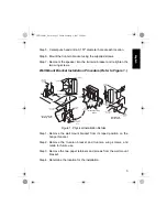
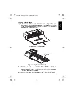
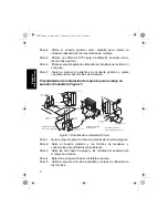
Trunnion Bracket Installation Procedure (Refer to Figure 1.)

Step 1. Remove the trunnion bracket by loosening the two wing screws.

Step 2. Remove the three paper retainers and screws from the trunnion

bracket.

Step 3. Remove the wall mount bracket from its taped position on the

hanger bracket, and retain for future use.

Step 4. Using the trunnion bracket as a template, mark the location of the

three desired mounting holes.

6871239M01_En.fm  Page 2  Friday, February 2, 2007  5:20 PM

Summary of Contents for RLN6257

Page 1: ...PA Speaker RLN6257 Accessories EN LAS BP FRC ID DE ES FR IT PR NL RU 简 cover fm Page 1 Thursday April 19 2007 11 10 AM ...

Page 2: ...cover fm Page 2 Thursday April 19 2007 11 10 AM ...

Page 3: ...permitting it to be tilted or angled for best results Vehicles Equipped With Airbags An airbag inflates with great force DO NOT place objects including communication equipment in the area over the airbag or in the airbag deployment area If the communication equipment is improperly placed and the airbag inflates this could cause serious injury Always mount the speaker securely with the supplied mou...

Page 4: ...tional use in place of wing screws 2 Installation These tools are required for installation Center punch Hammer Drill 1 4 Chuck 22 Twist Drill 0 157 for self tapping screws 38 Twist Drill 0 101 for self tapping screws Nut Driver 1 4 Nut Driver 5 16 Trunnion Bracket Installation Procedure Refer to Figure 1 Step 1 Remove the trunnion bracket by loosening the two wing screws Step 2 Remove the three p...

Page 5: ...emove the two paper retainers and screws from the wall mount bracket Step 4 Determine the location for the installation 0 101 2 56mm Diameter 6 20 x 1 2 Self Tapping Screw Wall Mounting Bracket Detail Wall Mounting Bracket NOTE The rear cover of the speaker and the circuit board must be temporarily removed to mount the hanger bracket Hanger Bracket Hanger Bracket Vehicle Window Window Mounting Det...

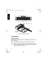
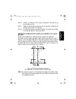
Page 6: ...y be subject to excessive strain or abuse it may be desirable to use both the trunnion mounting bracket and the wall mounting bracket In this case follow the procedures in both 2 2 and 2 3 but use the dimensions in Figure 2 to locate the hole centers Figure 2 Dual Trunnion and Wall Mount Dimensions NOTE Do not use Figure 2 as a template to drill holes for mounting It is only to be used as a refere...

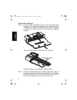
Page 7: ...tor Step 2 Insert the contacts into pin locations 12 or 16 for black wire pin 7 for red wire and pin 13 for microphone audio or pin 15 for microphone plus receive audio for blue wire on the accessory connector as shown in Figure 4 Step 3 Plug the accessory connector into the back of the mobile radio Figure 3a Wire Strain Relief Figure 3b Optional Strain Relief Optional strain relief with tie wrap ...

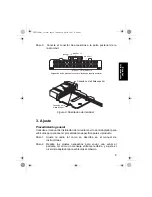
Page 8: ...l Step 2 Setup the conditions required to provide a signal to the speaker such as an incoming received message and set the vehicular adapter volume level to maximum pin 13 pin 12 pin 7 Connector Pinout Mapping Viewed from Rear of Connector Locking lance up on top row Locking lance down for bottom row Figure 4 Terminal Orientation pin 16 pin 15 6871239M01_En fm Page 6 Friday February 2 2007 5 20 PM...

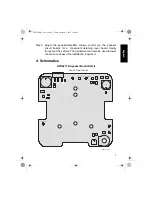
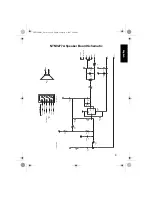
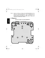
Page 9: ... The adjustment can also be used to lower minimum loudness if the installation requires it 4 Schematics NTN9277A Speaker Board Detail A AUD_IN AUD_OUT VIEWED FROM TOP SIDE BLK_WHT C1 C2 C3 C4 C5 C6 C7 C8 C9 C10 C12 C14 C15 GND R1 1 2 3 R2 R3 R4 R5 R6 R7 SHEILD SPKR SPKR_BLK_WHT 5 4 3 1 2 U1 MAEPF 26869 O 6871239M01_En fm Page 7 Friday February 2 2007 5 20 PM ...

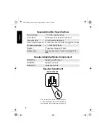
Page 10: ... than 10 distortion rated voltage Frequency response 1 3 dB 300 3000 Hz Speaker 5 permanent magnet 2 ohms Battery drain Standby less than 0 1 amp Full output 0 75 amp NTN9277A Speaker amplifier board RLN6257A Speaker and cable RKN4135A Interconnect cable ADJUST SPEAKER When the speaker is installed to XTVA NLD7654 it is recommended that the loudness adjustment be set as depicted above for best rec...

Page 11: ...1uF C1 10uF 500 R2 1 3 3 1 6 5 4 2 2 C12 01uF 560 R7 2 2K R1 3 GND 2 INV 1 NINV 4 OUT 5 SUP_VOLT BLK_WHT TDA2003 U1 SPKR SPKR_BLK_WHT GND AUD_OUT AUD_IN SHEILD BLK WHT BLK LS1 2 OHM A BLUE SHIELD BLK RED BLK WHT WHT AUD IN SHIELD GND A SPKR AUD OUT P1 CONNECTOR SHORT CABLE PCB EDGE CONNECTIONS SPKR 63B81078C99 O 6871239M01_En fm Page 9 Friday February 2 2007 5 20 PM ...

Page 12: ...de aire las bolsas de aire se inflan con gran fuerza NO coloque objetos incluyendo equipos de comunicación en el área que se encuentra encima de la bolsa de aire ni en el área de despliegue de la bolsa de aire Si el equipo de comunicación se coloca incorrectamente y la bolsa de aire se infla puede provocar lesiones graves Monte siempre el parlante con firmeza con los elementos de montaje provistos...

Page 13: ...l soporte giratorio y coloque el soporte para montaje en paredes en el parlante utilizando el soporte colgante Se entregan tornillos de seguridad que se pueden utilizar en lugar de los tornillos de mariposa 2 Instalación Necesitará las siguientes herramientas para llevar a cabo la instalación Punzón Martillo Taladro portabroca de 1 4 pulg Broca helicoidal Núm 22 0 157 pulg para tornillos autorrosc...

Page 14: ...nte Paso 3 Quite los dos topes de papel y los tornillos del soporte para montaje en paredes Paso 4 Determine el lugar donde se instalará el equipo Paso 5 Utilice el soporte a modo de plantilla y marque la ubicación de los tornillos MAEPF 26870 O Tornillo autorroscante 10 16 x 5 8 Tornillo autorroscante 10 16 x 5 8 Tornillo autorroscante 6 20 x 1 2 Tablero Tablero Cortafuegos Cortafuegos Consola o ...

Page 15: ...n uso intensivo es aconsejable utilizar tanto el soporte giratorio como el soporte para montaje en paredes Si éste es el caso siga los procedimientos de las secciones 2 2 y 2 3 pero utilice las dimensiones que se incluyen en la Figura 2 para ubicar los centros de los orificios Figura 2 Dimensiones para el soporte para paredes y el soporte giratorio combinados NOTA No utilice la Figura 2 como plant...

Page 16: ...os cables al conector Paso 2 Inserte los contactos tal como se indica en la Figura 4 pines 12 ó 16 para el cable negro pin 7 para el cable rojo y pin 13 para el audio del micrófono o pin 15 para el micrófono y recepción de audio para el cable azul en el accesorio de conexión Figura 3a Elemento para aliviar tensiones del cable Figura 3b Elemento opcional para aliviar tensiones Elemento para aliviar...

Page 17: ...dio tal como se describe en el manual de instrucciones Paso 2 Realice los ajustes necesarios para enviar una señal al parlante tal como un mensaje entrante recibido y ajuste el nivel del adaptador para vehículos al máximo pin núm 13 pin núm 12 pin núm 7 Asignación de los pines del conector visto desde la parte posterior Conexión en la hilera superior Conexión en la hilera inferior pin núm 16 pin n...

Page 18: ...hículo Si la instalación lo requiere también es posible utilizar el ajuste para reducir el nivel mínimo de volumen 4 Diagrama Detalle del tablero del parlante NTN9277A A AUD_IN AUD_OUT BLK_WHT C1 C2 C3 C4 C5 C6 C7 C8 C9 C10 C12 C14 C15 GND R1 1 2 3 R2 R3 R4 R5 R6 R7 SHEILD SPKR SPKR_BLK_WHT 5 4 3 1 2 U1 VISTO DESDE ARRIBA MAEPF 26869 O 6871239M01_es la fm Page 7 Thursday April 19 2007 11 40 AM ...

Page 19: ... de 10 de distorsión a la tensión nominal Respuesta de frecuencia 1 3 dB 300 3000 Hz Parlante imán permanente de 5 pulg 2 ohmios Purga de batería En espera menos de 0 1 amp Potencia máxima 0 75 amp NTN9277A Circuito de parlante amplificador RLN6257A Parlante y cable RKN4135A Cable de interconexión AJUSTE DEL PARLANTE Cuando se instale el parlante para XTVA NLD7654 se recomienda realizar el ajuste ...

Page 20: ...1uF C1 10uF 500 R2 1 3 3 1 6 5 4 2 2 C12 01uF 560 R7 2 2K R1 3 GND 2 INV 1 NINV 4 OUT 5 SUP_VOLT BLK_WHT TDA2003 U1 SPKR SPKR_BLK_WHT GND AUD_OUT AUD_IN SHEILD BLK WHT BLK LS1 2 OHM A BLUE SHIELD BLK RED BLK WHT WHT AUD IN SHIELD GND A SPKR AUD OUT SPKR CONECTOR P1 CABLE CORTO CONEXIONES DEL TABLERO DE CIRCUITOS IMPRESO 63B81078C99 O 6871239M01_es la fm Page 9 Thursday April 19 2007 11 40 AM ...

Page 21: ...airbag infla com grande força NÃO coloque objetos inclusive equipamentos de comunicação na área acima do airbag ou na área de estendimento do airbag Se o equipamento de comunicação não for colocado de forma adequada e o airbag inflar isso provocará ferimentos graves Monte sempre o alto falante de forma segura com o equipamento de montagem fornecido Um alto falante que não esteja montado em uma pos...

Page 22: ...r nas áreas inacessíveis Neste caso remova o suporte de munhão e conecte o alto falante no suporte de montagem na parede usando o suporte suspenso Os parafusos de segurança são incluídos para utilização opcional no lugar dos parafusos borboleta 2 Instalação Estas ferramentas são necessárias para a instalação Punção de bico Martelo Furadeira broca de 1 4 pol Broca espiral n 22 0 157 pol para parafu...

Page 23: ...porte de munhão e os parafusos borboleta e guarde os para uso futuro Etapa 3 Remova os dois retentores de papel e os parafusos do suporte de montagem na parede Etapa 4 Determine o local da instalação MAEPF 26870 O Tornillo autorroscante 10 16 x 5 8 Tornillo autorroscante 10 16 x 5 8 Tornillo autorroscante 6 20 x 1 2 Tablero Tablero Cortafuegos Cortafuegos Consola o piso Soporte giratorio Soporte g...

Page 24: ...s onde o alto falante pode estar sujeito ao uso excessivo talvez seja conveniente usar ambos os suportes de munhão e de montagem na parede Neste caso siga os procedimentos em 2 2 e 2 3 porém use as dimensões na Figura 2 para localizar os furos centrais Figura 2 Dimensões duplas de munhão e de montagem na parede NOTA Não siga a Figura 2 como um modelo para fazer os furos da montagem Ela deve ser us...

Page 25: ...ao conector Etapa 2 Insira os contatos nos pinos n 12 ou n 16 para o fio preto o pino n 7 para o fio vermelho e o pino n 13 do áudio do microfone ou o n 15 do microfone mais o áudio de recepção para o fio azul no conector do acessório como mostrado na Figura 4 Protetor contra torção opcional com braçadeira Figura 3a Protetor contra torção do fio Figura 3b Protetor contra torção opcional 6871239M01...

Page 26: ...nstrução do rádio Etapa 2 Determine as condições necessárias para fornecer um sinal ao alto falante como uma mensagem de recepção e ajuste o nível do volume do adaptador veicular para o máximo pino n 13 pino n 12 pino n 7 Esquema de pinagem do conector visto da parte traseira do conector Travamento da haste Travamento da haste inferior pino n 16 pino n 15 Figura 4 Orientação do terminal superior p...

Page 27: ...laramente em todo o veículo O ajuste também pode ser usado para abaixar o volume no mínimo se a instalação exigir isso 4 Esquema Detalhe da placa do alto falante NTN9277A A AUD_IN AUD_OUT BLK_WHT C1 C2 C3 C4 C5 C6 C7 C8 C9 C10 C12 C14 C15 GND R1 1 2 3 R2 R3 R4 R5 R6 R7 SHEILD SPKR SPKR_BLK_WHT 5 4 3 1 2 U1 VISTO DESDE ARRIBA MAEPF 26869 O 6871239M01_Pt Br fm Page 7 Tuesday April 24 2007 10 22 AM ...

Page 28: ...m nominal com menos de 10 de distorção Resposta de freqüência 1 3 dB 300 3000 Hz Alto falante Magneto permanente de 5 pol 2 ohms Corrente da bateria Espera menos que 0 1 amp Saída total 0 75 amp NTN9277A Placa do alto falante amplificador RLN6257A Alto falante e cabo RKN4135A Cabo de interconexão M A E P F 2 1 1 AJUSTE DEL PARLANTE Cuando se instale el parlante para XTVA NLD7654 se recomienda real...

Page 29: ...uF C1 10uF 500 R2 1 3 3 1 6 5 4 2 2 C12 01uF 560 R7 2 2K R1 3 GND 2 INV 1 NINV 4 OUT 5 SUP_VOLT BLK_WHT TDA2003 U1 SPKR SPKR_BLK_WHT GND AUD_OUT AUD_IN SHEILD BLK WHT BLK LS1 2 OHM A BLUE SHIELD BLK RED BLK WHT WHT AUD IN SHIELD GND A SPKR AUD OUT SPKR CONECTOR P1 CABLE CORTO CONEXIONES DEL TABLERO DE CIRCUITOS IMPRESO 63B81078C99 O 6871239M01_Pt Br fm Page 9 Tuesday April 24 2007 10 22 AM ...

Page 30: ...nt de communication dans la zone au dessus du coussin de sécurité gonflable ou dans la zone de déploiement du coussin de sécurité gonflable Si l équipement de communication est placé incorrectement et si le coussin de sécurité gonflable se gonfle ceci pourrait entraîner des blessures sérieuses Toujours monter le haut parleur de manière sûre avec le matériel de montage fourni Un haut parleur qui n ...

Page 31: ...op large pour passer dans des zones inaccessibles Dans ce cas enlever le support de tourillon et attacher le haut parleur au support de fixation murale en utilisant le support de palier pendant Des vis de sécurité sont fournies en option et il est possible de les utiliser à la place des vis papillon 2 Installation Les outils suivants sont requis pour l installation Pointeau Marteau Perceuse mandri...

Page 32: ...e fixation murale de sa position scellée sur le support de palier pendant Étape 2 Enlever le support de tourillon et les vis papillon et les conserver pour une utilisation ultérieure MAEPF 26870 O Tornillo autorroscante 10 16 x 5 8 Tornillo autorroscante 10 16 x 5 8 Tornillo autorroscante 6 20 x 1 2 Tablero Tablero Cortafuegos Cortafuegos Consola o piso Soporte giratorio Soporte giratorio Soporte ...

Page 33: ... de fixation murale Installation du tourillon double et du montage mural Dans certaines installations comme les bus d école où le haut parleur peut faire l objet de pression excessive ou peut être malmené il peut être souhaitable d utiliser à la fois le support de tourillon et le support de montage mural Dans ce cas suivre les procédures des étapes 2 2 et 2 3 mais utiliser les dimensions de Figure...

Page 34: ...e indiqué à la Figure 3b et utiliser un collier de serrage pour sécuriser les fils au connecteur Étape 2 Insérer les contacts dans les emplacements de connexion No 12 ou No 16 pour le câble noir la connexion No 7 pour le câble rouge ou la connexion No 13 pour le microphone plus audio de réception pour le câble bleu sur le connecteur d accessoire comme indiqué à la Figure 4 Réducteur de tension opt...

Page 35: ... 2 Configurer les conditions requises pour fournir un signal au haut parleur comme un message reçu à l entrée et monter au maximum le niveau de volume de l adaptateur véhiculaire connexion No 13 connexion No 12 connexion No 7 Association connecteur connexion vue de l arrière du connecteur Lance de verrouillage vers le haut Lance de verrouillage vers le bas pour la rangée inférieure connexion No 16...

Page 36: ...st possible également d effectuer un réglage pour diminuer l intensité minimum si l installation le nécessite 4 Schémas Détail du circuit du haut parleur NTN9277A A AUD_IN AUD_OUT BLK_WHT C1 C2 C3 C4 C5 C6 C7 C8 C9 C10 C12 C14 C15 GND R1 1 2 3 R2 R3 R4 R5 R6 R7 SHEILD SPKR SPKR_BLK_WHT 5 4 3 1 2 U1 VISTO DESDE ARRIBA MAEPF 26869 O 6871239M01_fr ca fm Page 7 Thursday April 19 2007 3 38 PM ...

Page 37: ...e distorsion tension nominale Réponse de fréquence 1 3 dB 300 3000 Hz Haut parleur aimant permanent 5 pouce 2 ohms Vitesse d épuisement de l accumulateur Attente moins de 0 1 amp réception totale 0 75 amp NTN9277A Circuit du haut parleur amplificateur RLN6257A Haut parleur et câble RKN4135A Câble de liaison AJUSTE DEL PARLANTE Cuando se instale el parlante para XTVA NLD7654 se recomienda realizar ...

Page 38: ...F C1 10uF 500 R2 1 3 3 1 6 5 4 2 2 C12 01uF 560 R7 2 2K R1 3 GND 2 INV 1 NINV 4 OUT 5 SUP_VOLT BLK_WHT TDA2003 U1 SPKR SPKR_BLK_WHT GND AUD_OUT AUD_IN SHEILD BLK WHT BLK LS1 2 OHM A BLUE SHIELD BLK RED BLK WHT WHT AUD IN SHIELD GND A SPKR AUD OUT SPKR CONECTOR P1 CABLE CORTO CONEXIONES DEL TABLERO DE CIRCUITOS IMPRESO 63B81078C99 O 6871239M01_fr ca fm Page 9 Thursday April 19 2007 3 38 PM ...

Page 39: ...rena dapat dimiringkan atau diputar sesuai sudut kemiringan yang diperlukan Kendaraan yang Dilengkapi Airbag Airbag akan membuka dengan tenaga yang sangat besar JANGAN meletakkan benda benda termasuk peralatan komunikasi di atas daerah airbag atau di dalam area pembukaan airbag Jika peralatan komunikasi diletakkan di tempat yang salah dan airbag membuka hal tersebut dapat menyebabkan cedera Pasang...

Page 40: ...ngan menggunakan braket penggantung Sekrup pengaman tersedia sebagai pengganti sekrup sayap bila perlu 2 Pemasangan Berikut adalah alat alat yang diperlukan untuk pemasangan Pembolong Palu Bor Kunci Mata Bor 1 4 Mata Bor Ulir 0 157 22 untuk sekrup tanam Mata Bor Ulir 0 101 38 untuk sekrup tanam Obeng Soket 1 4 Obeng Soket 5 16 Prosedur Pemasangan Braket Putar Lihat Gambar 1 Langkah 1 Lepaskan brak...

Page 41: ...p sekrup dari braket dudukan untuk dinding Langkah 4 Tentukan lokasi pemasangan Langkah 5 Dengan menggunakan braket sebagai dasar tandai lokasi untuk sekrup sekrup Langkah 6 Gunakan pembolong dan bor untuk membuat lubang berdiameter 0 101 pada kedua tanda 0 101 2 56mm Diameter 6 20 x 1 2 Self Tapping Screw Wall Mounting Bracket Detail Wall Mounting Bracket NOTE The rear cover of the speaker and th...

Page 42: ... bahwa diperlukan pemasangan braket putar dan braket dudukan dinding Untuk melakukan hal tersebut ikuti prosedur pada 2 2 dan 2 3 tetapi gunakan dimensi pada Gambar 2 untuk menentukan bagian tengah lubang Gambar 2 Dimensi Ganda Braket Putar dan Dudukan Dinding CATATAN Jangan menggunakan Gambar 2 sebagai dasar untuk mengebor lubang lubang pemasangan Ini hanyalah digunakan sebagai referensi penggamb...

Page 43: ...engan pengikat kabel Langkah 2 Masukkan kontak kontak ke lokasi lokasi pin 12 atau 16 untuk kawat hitam pin 7 untuk kawat merah dan pin 13 untuk audio mikrofon atau pin 15 untuk mikrofon plus audio penerimaan untuk kawat biru pada konektor aksesori seperti pada Gambar 4 Pengimbang regangan dengan pengikat opsional Gambar 3a Pengimbang Regangan Kabel Gambar 3b Pengimbang Regangan opsional 6871239M0...

Page 44: ...i yang tertera di dalam manual petunjuk pesawat radio Langkah 2 Siapkan kondisi yang diperlukan untuk pengiriman sinyal ke pengeras suara seperti pesan penerimaan masuk dan set level volume adaptor kendaraan ke maksimum pin 13 pin 12 pin 7 Diagram Pin Konektor Tampak Belakang Tuas pengunci menghadap Tuas pengunci untuk barisan bawah pin 16 pin 15 Gambar 4 Orientasi Terminal ke atas pada barisan at...

Page 45: ...lan juga dapat digunakan untuk menurunkan tingkat kekerasan suara bila diperlukan 4 Gambar Skematik NTN9277A Rincian Papan Pengeras Suara A AUD_IN AUD_OUT VIEWED FROM TOP SIDE BLK_WHT C1 C2 C3 C4 C5 C6 C7 C8 C9 C10 C12 C14 C15 GND R1 1 2 3 R2 R3 R4 R5 R6 R7 SHEILD SPKR SPKR_BLK_WHT 5 4 3 1 2 U1 MAEPF 26869 O TAMPAK ATAS 6871239M01_Id fm Page 7 Tuesday April 24 2007 10 25 AM ...

Page 46: ... watt distorsi kurang dari 10 pada tegangan kerja Respons frekuensi 1 3 dB 300 3000 Hz Pengeras Suara magnet permanen 5 2 ohm Pemakaian baterai Standby kurang dari 0 1 amp Keluaran penuh 0 75 amp NTN9277A Papan pengeras suara amplifier RLN6257A Pengeras suara dan kabel RKN4135A Kabel interkoneksi ADJUST SPEAKER When the speaker is installed to XTVA NLD7654 it is recommended that the loudness adjus...

Page 47: ... 220pF C8 01uF C1 10uF 500 R2 1 3 3 1 6 5 4 2 2 C12 01uF 560 R7 2 2K R1 3 GND 2 INV 1 NINV 4 OUT 5 SUP_VOLT BLK_WHT TDA2003 U1 SPKR SPKR_BLK_WHT GND AUD_OUT AUD_IN SHEILD BLK WHT BLK LS1 2 OHM A BLUE SHIELD BLK RED BLK WHT WHT AUD IN SHIELD GND A SPKR AUD OUT P1 CONNECTOR SHORT CABLE PCB EDGE CONNECTIONS SPKR 63B81078C99 O 6871239M01_Id fm Page 9 Tuesday April 24 2007 10 25 AM ...

Page 48: ... 已经安装在扬声器上 可以将扬声器临时挂在车辆的突出部位 如车窗上 在此情况下 您必须松开两个翼形螺钉 将扬声器从旋转支架 上取下 如果旋转支架对于某些要安装的区域显得过大 则可以用墙壁安装支架来 进行永久安装 在此情况下 取下旋转支架 使用悬挂支架将扬声器固定 在墙壁安装支架上 此时使用安全螺钉代替翼形螺钉 配备安全气囊的车辆 气囊膨胀时会产生很大的力量 不得将包括 通信设备在内的任何物品放在气囊上方或气囊展开时占用的范围 内 如果通信设备摆放不当 气囊展开时可能会造成严重的伤害 务必使用附带的安装构件牢固地安装扬声器 如果将扬声器安装 在不固定的位置 则有可能干扰车辆的正常运行 安装螺钉可能会使车辆上某些安装表面内部的电缆和电线破损 注意避免将支架安装在这些位置 如果将支架安装在不牢固或空心的安装表面上 支架可能会松 脱 发生撞击时 设备可能会脱离 在安装支架的位置 自攻螺 钉必须能够...

Page 49: ...旋钻 0 101 螺帽起子 1 4 螺帽起子 5 16 旋转支架安装步骤 参阅图 1 步骤 1 松开两个翼形螺钉 取下旋转支架 步骤 2 从旋转支架上取下三个纸护圈和螺钉 步骤 3 将墙壁安装支架从悬挂支架的固定位置上取下 并保留好以备后 用 步骤 4 将旋转支架用作模板 标出三个所需安装孔的位置 步骤 5 在每个孔的位置钻一个 0 157 直径的孔 步骤 6 使用附带的螺钉安装旋转支架 步骤 7 重新将扬声器装到旋转支架上 上紧两颗翼形螺钉 6871239M01_ZhS fm Page 2 Friday April 20 2007 8 02 AM ...

Page 50: ... 标出螺钉位置 步骤 6 在两个螺钉位置钻 0 101 直径的孔 步骤 7 使用附带的螺钉将墙壁安装支架安装在表面上 步骤 8 将悬挂支架 固定在扬声器上 牢牢扣入墙壁安装支架中 MAEPF 26870 O 䔺に 10 16 x 5 8 㞾ᬏ㶎䩝 10 16 x 5 8 㞾ᬏ㶎䩝 6 20 x 1 2 㞾ᬏ㶎䩝 Ҿ㸼Ⲭ Ҿ㸼Ⲭ 䰆 䰆 ࠊৄ ഄᵓ ᮟ䕀ᬃᶊ ᮟ䕀ᬃᶊ ᣖᬃᶊ ᣖᬃᶊ 0 157 3 99mm Ⳉᕘ 0 101 2 56mm Ⳉᕘ ࠄ䰆 ᅝ㺙 ຕᅝ㺙ᬃᶊ ᮟ䕀ᬃᶊᅝ㺙䆺 䔺にᅝ㺙䆺 ຕᅝ㺙ᬃᶊ䆺 ᛣ ᡀໄ ৢⲪ 䏃ᵓᖙ乏Јᯊ পϟҹᅝ㺙 ᣖᬃᶊDŽ 6871239M01_ZhS fm Page 3 Friday April 20 2007 8 02 AM ...

Page 51: ...需要使用 在此情况下 按照 2 2 和 2 3 中的步骤 安装 但请使用图 2 中的尺寸来确定孔的中心 图 2 同时使用旋转 和墙壁安装的尺寸 注意 安装时不要将图 2 用作模板来钻孔 它仅供参考用来显示相对的位 置 1 92 48 77mm 0 96 24 38mm 2 31 58 67mm 1 155 29 34mm 2 56 65 02mm 0 375 9 53mm MAEPF 26871 O ຕᅝ㺙ᬃᶊ ᮟ䕀ᬃᶊ 6871239M01_ZhS fm Page 4 Friday April 20 2007 8 02 AM ...

Page 52: ...个附件连接到车载对讲机 请按图 3b 所示穿引电线 并用扎线带固定电线 步骤 2 对于黑色线 将触点插入插孔位置 12 或 16 对于红色线插入 插孔位置 7 对于麦克风音频插入插孔位置 13 或 15 附件接 口上的蓝色线用于接收音频 如图 4 所示 步骤 3 将附件接口插入车载对讲机后面 用扎线带包扎的 可选耐扭式线扣 图 3a 耐扭式线扣 图 3b 可选耐扭式线扣 6871239M01_ZhS fm Page 5 Friday April 20 2007 8 02 AM ...

Page 53: ...手册调整对讲机 步骤 2 设置所需条件以提供一个信号 例如接收到的信息 到扬声器 并 将车载转接器音量设到最大 步骤 3 调整扬声器 放大器音量控制 在扬声器电路板上 以便获得一 个能在车内清楚听到所放声音的适合收听音量 如果安装需要 此 调整还可以用于降低最小响度 13 插孔 12 插孔 7 插孔 接口后部插脚图 下排锁扣 缺口朝下 16 插孔 15 插孔 图 4 接触端方向 上排锁扣缺口朝上 6871239M01_ZhS fm Page 6 Friday April 20 2007 8 02 AM ...

Page 54: ...7 简 体 中 文 4 电路图 NTN9277A 扬声器电路板详图 6871239M01_ZhS fm Page 7 Friday April 20 2007 8 02 AM ...

Page 55: ...输入音量 输入灵敏度 全输出 0 5 V 到扬声器的音频输出 6 瓦 失真小于 10 额定电压 频响 1 3 dB 300 3000 Hz 扬声器 5 永磁体 2 欧姆 蓄电池 空闲 小于 0 1 安 全输出 0 75 安 NTN9277A 扬声器 放大器板 RLN6257A 扬声器和电缆 RKN4135A 互连电缆 䇗ᭈᡀໄ ᔧℸᡀໄ 䖲 ࠄ XTVA NLD7654 ᯊˈ ᓎ䆂ᣝϞ䴶ⱘ䇈ᯢ䇗ᭈડᑺˈҹ㦋ᕫ Շ ⱘໄ ᬊ ᱄ᑺDŽ 6871239M01_ZhS fm Page 8 Friday April 20 2007 8 02 AM ...

Page 56: ...9 简 体 中 文 NTN9277A 扬声器电路图 6871239M01_ZhS fm Page 9 Friday April 20 2007 8 02 AM ...

Page 57: ...INE Gegenstände einschließlich Funkgeräte abgelegt oder installiert werden Wird eine Kommunikationseinrichtung z B ein Funkgerät unsachgemäß an ungeeigneter Stelle installiert und der Airbag bläht sich auf kann dies zu schweren Verletzungen führen Der Durchsageverstärker muss stets mit den jeweils mitgelieferten Befestigungsteilen eingebaut werden Ein nicht fest eingebauter Durchsageverstärker kan...

Page 58: ...der Durchsageverstärker mit Hilfe der Aufhängung an der Wandhalterung zu befestigen Sicherheitsschrauben zur wahlweisen Verwendung anstelle der Flügelschrauben werden mitgeliefert 2 Installation Für die Montage werden die folgenden Werkzeuge benötigt Zentrierkörner Hammer Bohrer 1 4 Spannkopf 22 Spiralbohrer 0 157 für Schneidschrauben 38 Spiralbohrer 0 101 für Schneidschrauben Steckschlüssel 1 4 S...

Page 59: ...alterung als Schablone um die Positionen der drei Schrauben zu kennzeichnen 0 101 2 56mm Diameter 6 20 x 1 2 Self Tapping Screw Wall Mounting Bracket Detail Wall Mounting Bracket NOTE The rear cover of the speaker and the circuit board must be temporarily removed to mount the hanger bracket Hanger Bracket Hanger Bracket Vehicle Window Window Mounting Detail Trunnion Bracket Mounting Detail Dashboa...

Page 60: ...ll wünschenswert und erforderlich sowohl Haltebügel als auch Wandhalterung zu verwenden In diesem Fall gehen Sie wie in 2 2 und 2 3 beschrieben vor verwenden jedoch die Abmessungen in Abb 2 für die Befestigungslöcher Abb 2 Doppelt abgesicherte Anbringung mit Haltebügel und Wandhalterung HINWEIS Abb 2 darf nicht als Vorlage für die erforderlichen Befestigungsbohrungen benutzt werden Die Abbildung d...

Page 61: ...Sie die Anschlussstifte in die Pin Stellen Nr 12 oder Nr 16 für das schwarze Kabel Pin Nr 7 für das rote Kabel und Pin Nr 13 für Mikrofonaudio oder Pin Nr 15 für Mikrofon plus Empfangsaudio für das blaue Kabel am Zubehöranschluss wie in Abb 4 gezeigt Schritt 3 Stecken Sie den Zubehörstecker an der Rückseite des Funkgeräts ein Abb 3a Zugentlastung Abb 3b Wahlweise Zugentlastung Wahlweise Zugentlast...

Page 62: ...Leitung eines Signals an den Durchsageverstärker wie z B eine ankommende empfangene Nachricht erforderlichen Einstellungen durch und stellen Sie den Lautstärkepegel des Fahrzeugadapters auf maximale Lautstärke ein Pin Nr 13 Pin Nr 12 Pin Nr 7 Anschlussstiftanordnung Ansicht von der Sicherung oben in Sicherung unten für untere Reihe Abb 4 Ausrichtung der Anschlüsse Pin Nr 16 Pin Nr 15 Rückseite des...

Page 63: ...st Sofern die Installation dies erfordert kann die Mindestlautstärke auch leiser gestellt werden 4 Schaltpläne NTN9277A Lautsprecherschaltung Detail A AUD_IN AUD_OUT ANSICHT VON OBEN SCHW_WEISS C1 C2 C3 C4 C5 C6 C7 C8 C9 C10 C12 C14 C15 MASSE R1 1 2 3 R2 R3 R4 R5 R6 R7 ABSCHIRMUNG LTSPR LTSPR_SCHW_WEISS 5 4 3 1 2 U1 MAEPF 26869 O 6871239M01_DE fm Page 7 Friday April 20 2007 10 24 AM ...

Page 64: ...et 2 Ohm Stromverbrauch Standby Weniger als 0 1 A Volle Ausgabe 0 75 A NTN9277A Lautsprecher Verstärkerschaltung RLN6257A Lautsprecher und Kabel RKN4135A Verbindungskabel ADJUST SPEAKER When the speaker is installed to XTVA NLD7654 it is recommended that the loudness adjustment be set as depicted above for best receive audio clarity LAUTSPRECHER EINSTELLEN Wird der Lautsprecher mit dem XTVA NLD765...

Page 65: ...ND AUD_OUT AUD_IN SHEILD BLK WHT BLK LS1 2 OHM A BLUE SHIELD BLK RED BLK WHT WHT AUD IN SHIELD GND A SPKR AUD OUT P1 CONNECTOR SHORT CABLE PCB EDGE CONNECTIONS SPKR 63B81078C99 O LTSPR SCHW SCHW WEISS PCB RAND ANSCHLÜSSE BLAU ABSCHIRMUNG ABSCHIRMUNG SCHW MASSE ROT SCHW_WEISS LTSPR WEISS KURZES KABEL P1 ANSCHLUSS ABSCHIRMUNG MASSE LTSPR LTSPR_SCHW_WEISS SCHW WEISS 0 1 µF 0 22 µF 0 01 µF SPEISUNG V ...

Page 66: ...quipement au dessus d un airbag ou dans sa zone de déploiement Un équipement placé ou installé dans cette zone de déploiement peut être projeté avec violence à la suite de l ouverture de l airbag Il pourrait alors blesser gravement les passagers Le haut parleur doit toujours être installé avec le support fourni Un haut parleur qui n est pas solidement fixé peut gêner la conduite du véhicule La pos...

Page 67: ...Dans ce cas retirez le support horizontal et utilisez le support de suspension pour fixer le boîtier sur le support vertical Les vis de sécurité sont fournies pour remplacer les vis à molette 2 Installation Vous aurez besoin des outils suivants pour installer votre haut parleur amplificateur Poinçon Marteau Perceuse mandrin 6 3 mm 1 4 Foret No 22 4 mm 0 157 pour les vis autotaraudeuses Foret No 38...

Page 68: ...ng Screw Wall Mounting Bracket Detail Wall Mounting Bracket NOTE The rear cover of the speaker and the circuit board must be temporarily removed to mount the hanger bracket Hanger Bracket Hanger Bracket Vehicle Window Window Mounting Detail Trunnion Bracket Mounting Detail Dashboard Firewall Trunnion Bracket To Firewall Mounting or Dashboard Firewall 10 16 x 5 8 Self Tapping Screw 0 157 3 99mm Dia...

Page 69: ...tions des sections 2 2 et 2 3 mais avec les dimensions présentées dans la Figure 2 pour positionner les trous à forer Figure 2 Dimensions pour l installation double supports horizontal et vertical REMARQUE N utilisez pas la Figure 2 comme gabarit pour marquer les trous de l installation Elle n est qu un guide approximatif pour vous aider à reconnaître les mesures à effectuer 1 92 48 77mm 0 96 24 3...

Page 70: ...ache Étape 2 Insérez le contact du fil noir dans la broche 12 ou 16 du fil rouge dans la broche 7 de l audio micro dans la broche 13 ou du fil bleu du microphone plus réception audio dans la broche 15 du connecteur d accessoire Figure 4 Étape 3 Branchez le connecteur d accessoire à l arrière du poste mobile Figure 3a Décharge de traction Figure 3b Décharge de traction optionnelle Décharge de tract...

Page 71: ...audible dans le haut parleur par exemple un message entrant et réglez le niveau du volume de la radio de l adaptateur au maximum Broche No 13 Broche No 12 Broche No 7 Branchement sur les broches du connecteur vu de l arrière du connecteur Verrouillage de fiche orienté vers le Verrouillage de fiche orienté vers le bas sur Figure 4 Orientation des bornes Broche No 16 Broche No 15 haut sur la rangée ...

Page 72: ... réglage peut servir à réduire le niveau minimal si nécessaire 4 Schémas électriques Détail de la carte du haut parleur NTN9277A A ENTRÉE AUDIO SORTIE AUDIO VUE SUPÉRIEURE NOIR BLANC C1 C2 C3 C4 C5 C6 C7 C8 C9 C10 C12 C14 C15 MASSE R1 1 2 3 R2 R3 R4 R5 R6 R7 BLINDAGE HP HP NOIR BLANC 5 4 3 1 2 U1 MAEPF 26869 O 6871239M01_FR fm Page 7 Friday April 20 2007 10 52 AM ...

Page 73: ...anent 127 mm 2 ohms Consommation Veille moins de 0 1 amp Débit maxi 0 75 amps NTN9277A Carte du haut parleur amplificateur RLN6257A Haut parleur et câble RKN4135A Câble de connexion ADJUST SPEAKER When the speaker is installed to XTVA NLD7654 it is recommended that the loudness adjustment be set as depicted above for best receive audio clarity POUR RÉGLER LE HAUT PARLEUR Lorsque le haut parleur es...

Page 74: ...D BLK WHT BLK LS1 2 OHM A BLUE SHIELD BLK RED BLK WHT WHT AUD IN SHIELD GND A SPKR AUD OUT P1 CONNECTOR SHORT CABLE PCB EDGE CONNECTIONS SPKR 63B81078C99 O SORTIE AUDIO 0 1 uF 0 22 uF TENSION ALIM SORTIE MASSE C5 0 1 uF R5 2 2 C3 0 47 uF C8 0 01 uF C12 0 01 uF R1 2 2 K ENTRÉE AUDIO BLINDAGE MASSE HP HP NOIR BLANC NOIR BLANC CONNECTEUR P1 BLEU BLINDAGE NOIR ROUGE NOIR BLANC BLANC CABLE COURT ENTRÉE...

Page 75: ...inclinar o girar para obtener mejores resultados En los vehículos equipados con airbag éstos se inflan con gran fuerza NO coloque objetos como por ejemplo el equipo de comunicaciones en la superficie que cubre el airbag ni en el área de despliegue de éste Si no se ha colocado el equipo de comunicaciones de forma adecuada y el airbag se infla pueden producirse lesiones graves Monte siempre el altav...

Page 76: ...rias las herramientas siguientes Punzón Martillo Taladro portabroca de 6 35 mm 1 4 in Broca helicoidal del número 22 3 98 mm 0 157 in para los tornillos con rosca cortante Broca helicoidal del número 38 2 56 mm 0 101 in para los tornillos con rosca cortante Llave para tuercas de 6 35 mm 1 4 in Llave para tuercas de 7 93 mm 5 16 in Procedimiento de instalación del soporte giratorio consulte la figu...

Page 77: ...iameter 6 20 x 1 2 Self Tapping Screw Wall Mounting Bracket Detail Wall Mounting Bracket NOTE The rear cover of the speaker and the circuit board must be temporarily removed to mount the hanger bracket Hanger Bracket Hanger Bracket Vehicle Window Window Mounting Detail Trunnion Bracket Mounting Detail Dashboard Firewall Trunnion Bracket To Firewall Mounting or Dashboard Firewall 10 16 x 5 8 Self T...

Page 78: ... 2 3 pero utilice las dimensiones de la figura 2 para localizar los centros de los agujeros Figura 2 Instalación del soporte mural y del soporte giratorio NOTA No utilice la figura 2 como modelo para taladrar los agujeros para el montaje Solo se debe usar como una referencia en la que figuran las medidas más importantes 1 92 48 77mm 0 96 24 38mm 2 31 58 67mm 1 155 29 34mm 2 56 65 02mm 0 375 9 53mm...

Page 79: ... Paso 2 Inserte los contactos en los pines 12 y 16 para el cable negro en el pin 7 para el cable rojo y en el pin 14 para el sonido del micrófono o en el pin 15 para el micrófono y recibir así el sonido en el cable azul del conector accesorio como se muestra en la figura 4 Paso 3 Enchufe el conector accesorio en la parte trasera del transceptor móvil Figura 3a Protector del cable Figura 3b Protect...

Page 80: ...tor Paso 2 Configure las condiciones necesarias para enviar una señal al altavoz como un mensaje entrante recibido y ajuste el nivel de volumen del adaptador del vehículo al máximo Pin 13 Pin 12 Pin 7 Asignación de pines del conector vista desde Varilla de cierre hacia arriba Varilla de cierre hacia Figura 4 Orientación del terminal Pin 16 Pin 15 la parte posterior del conector en la fila superior...

Page 81: ...uede utilizar para disminuir el volumen mínimo si la instalación lo requiere 4 Esquema Detalle de la placa del altavoz NTN9277A A ENT_AUD SAL_AUD VISTA DESDE LA PARTE SUPERIOR NEGRO_BLANCO C1 C2 C3 C4 C5 C6 C7 C8 C9 C10 C12 C14 C15 CONEXIÓN A TIERRA R1 1 2 3 R2 R3 R4 R5 R6 R7 BLINDAJE ALTAVOZ ALTAVOZ_NEGRO_BLANCO 5 4 3 1 2 U1 MAEPF 26869 O 6871239M01_ES fm Page 7 Monday April 23 2007 8 42 AM ...

Page 82: ... permanente de 0 174 mm 2 ohmios Consumo de la batería Modo de pausa menos de 0 1 amperios pleno ren dimiento 0 75 amperios NTN9277A Placa del altavoz amplificador RLN6257A Altavoz y cable RKN4135A Cable de interconexión ADJUST SPEAKER When the speaker is installed to XTVA NLD7654 it is recommended that the loudness adjustment be set as depicted above for best receive audio clarity AJUSTE DEL ALTA...

Page 83: ...HM A BLUE SHIELD BLK RED BLK WHT WHT AUD IN SHIELD GND A SPKR AUD OUT P1 CONNECTOR SHORT CABLE PCB EDGE CONNECTIONS SPKR 63B81078C99 O SAL_AUD ENT_AUD BLINDAJE CONEXIÓN A TIERRA ALTAVOZ ALTAVOZ_ NEGRO_BLANCO NEGRO BLANCO 2 OHMIOS ALTAVOZ NEGRO NEGRO_BLANCO CONECTOR P1 AZUL ENT AUD BLINDAJE BLINDAJE NEGRO CONEXIÓN A TIERRA ROJO NEGRO_BLANCO ALTAVOZ BLANCO SAL AUD CABLE CORTO CONEXIONES DEL EXTREMO ...

Page 84: ... motivo NON situare oggetti compresi gli apparecchi radio sopra l area dove sono alloggiati gli airbag o nella loro area di azione Se gli apparecchi radio sono situati nell area di azione dell airbag e questo si gonfia l unità può essere scagliata con grande forza e causare lesioni gravi agli occupanti del veicolo L altoparlante deve essere sempre fissato saldamente alla superficie prescelta con l...

Page 85: ... a gancio Il kit comprende anche viti di fissaggio da utilizzarsi al posto delle viti ad alette 2 Installazione Per l installazione è necessario disporre di centratore con punzone martello trapano portapunte da 1 4 punta elicoidale n 22 3 99 mm per le viti autofilettanti punta elicoidale n 38 2 56 mm per le viti autofilettanti chiave per dado 1 4 chiave per dado 5 16 Installazione con staffa orien...

Page 86: ...il Wall Mounting Bracket NOTE The rear cover of the speaker and the circuit board must be temporarily removed to mount the hanger bracket Hanger Bracket Hanger Bracket Vehicle Window Window Mounting Detail Trunnion Bracket Mounting Detail Dashboard Firewall Trunnion Bracket To Firewall Mounting or Dashboard Firewall 10 16 x 5 8 Self Tapping Screw 0 157 3 99mm Diameter Trunnion Bracket 10 16 x 5 8 ...

Page 87: ...o utilizzare assieme le staffe orientabile e da muro In tale evenienza eseguire quanto descritto nelle sezioni 2 2 e 2 3 ma facendo riferimento alle dimensioni riportate nella Figura 2 per individuare il centro dei fori Figura 2 Dimensioni per l installazione con le staffe orientabile e da muro NOTA non utilizzare la Figura 2 come sagoma per trapanare i fori di montaggio bensì quale riferimento pe...

Page 88: ...ccessori come indicato nella Figura 4 filo nero nel pin 12 o 16 filo rosso nel pin 7 e filo blu per l audio del microfono nel pin 13 oppure per l audio del microfono più ricevitore nel pin 15 3 Collegare il connettore accessori alla parte posteriore della radiomobile Figura 3a Dispositivo antitrazione per fili Figura 3b Dispositivo antitrazione opzionale Optional strain relief with tie wrap Dispos...

Page 89: ...isposizioni necessarie per instradare il segnale nell altoparlante come un messaggio in ricezione quindi impostare il volume dell adattatore veicolare sul livello massimo pin 13 pin 12 pin 7 Mappaggio dei pin out del connettore Vista posteriore Fila superiore linguetta Fila inferiore linguetta Figura 4 Orientamento dei terminali pin 16 pin 15 d aggancio rivolta verso l alto d aggancio rivolta vers...

Page 90: ...zione lo richiede la regolazione permette anche di abbassare il livello di loudness al minimo 4 Diagrammi schematici Particolare della scheda dell altoparlante NTN9277A A AUD_IN AUD_OUT VISTA DALLA PARTE SUPERIORE BLK_WHT C1 C2 C3 C4 C5 C6 C7 C8 C9 C10 C12 C14 C15 GND R1 1 2 3 R2 R3 R4 R5 R6 R7 SCHERMO SPKR SPKR_BLK_WHT 5 4 3 1 2 U1 MAEPF 26869 O 6871239M01_IT fm Page 7 Monday April 23 2007 8 48 A...

Page 91: ...Altoparlante magnete permanente 5 2 ohm Consumo batteria Stand by meno di 0 1 amp potenza d uscita totale 0 75 amp NTN9277A Scheda per altoparlante amplificatore RLN6257A Altoparlante e cavo RKN4135A Cavo per interconnessione ADJUST SPEAKER When the speaker is installed to XTVA NLD7654 it is recommended that the loudness adjustment be set as depicted above for best receive audio clarity REGOLAZION...

Page 92: ...V 4 OUT 5 SUP_VOLT BLK_WHT TDA2003 U1 SPKR SPKR_BLK_WHT GND AUD_OUT AUD_IN SHEILD BLK WHT BLK LS1 2 OHM A BLUE SHIELD BLK RED BLK WHT WHT AUD IN SHIELD GND A SPKR AUD OUT P1 CONNECTOR SHORT CABLE PCB EDGE CONNECTIONS SPKR 63B81078C99 O 220Pf 0 1Uf 220Uf 0 1Uf 100Uf CONNETTORE P1 BLU SCHERMO SCHERMO ROSSO CAVO CORTO CONNESSIONE AI BORDI DELLA PCB SCHERMO 0 1Uf 0 22Uf 2 2K 1000Pf 0 047Uf 220Pf 0 01U...

Page 93: ...mitindo lhe incliná lo ou curvá lo para obter os melhores resultados Veículos Equipados com Airbags Um airbag enche com muita força NÃO coloque objectos incluindo equipamento de comunicação na área sobre o airbag ou na área de accionamento do mesmo Se o equipamento de comunicação não for colocado no local correcto e o airbag encher podem ocorrer ferimentos graves O altifalante deve sempre ser mont...

Page 94: ... 2 Instalação Para a instalação são necessárias as ferramentas que se seguem Punção Martelo Perfuradora com bucha de 1 4 Broca n º 22 0 157 para parafusos auto roscantes Broca n º 38 0 101 para parafusos auto roscantes Chave de porcas de 1 4 Chave de porcas de 5 16 Procedimento de Instalação do Suporte com Munhão Ver Figura 1 Passo 1 Remova o suporte com munhão desapertando os dois parafusos de or...

Page 95: ...ail Wall Mounting Bracket NOTE The rear cover of the speaker and the circuit board must be temporarily removed to mount the hanger bracket Hanger Bracket Hanger Bracket Vehicle Window Window Mounting Detail Trunnion Bracket Mounting Detail Dashboard Firewall Trunnion Bracket To Firewall Mounting or Dashboard Firewall 10 16 x 5 8 Self Tapping Screw 0 157 3 99mm Diameter Trunnion Bracket 10 16 x 5 8...

Page 96: ... Neste caso siga os procedimentos descritos em 2 2 e 2 3 mas utilize as dimensões da Figura 2 para determinar os centros dos orifícios Figura 2 Dimensões para Instalação Dupla de Suporte com Munhão e Suporte de Montagem na Parede NOTA não utilize a Figura 2 como modelo para perfurar os orifícios de montagem Utilize a apenas como referência para as medidas relevantes 1 92 48 77mm 0 96 24 38mm 2 31 ...

Page 97: ... eléctricos na ficha Passo 2 Insira os contactos do fio preto nos pinos n º 12 ou n º 16 do fio vermelho no pino n º 7 do fio azul no pino n º 13 para o áudio do microfone ou no pino n º 15 para o microfone e recepção de áudio na ficha acessória conforme ilustrado na Figura 4 Passo 3 Ligue a ficha acessória na parte de trás do rádio móvel Figura 3a Aperta cabos Figura 3b Aperta cabos Opcional Aper...

Page 98: ...eleça as condições necessárias para enviar um sinal para o altifalante como por exemplo a recepção de uma mensagem e ajuste o nível do volume do adaptador para veículos para o máximo pino n º 13 pino n º12 pino n º 7 Esquema de Conexão de Pinos da Ficha Lança de engate para Lança de engate para baixo na fila de baixo Figura 4 Orientação de Terminais pino n º 16 pino n º 15 Vista por Trás cima na f...

Page 99: ...r necessário também é possível usar o ajuste para reduzir o volume mínimo 4 Esquema Vista Pormenorizada da Placa do Altifalante NTN9277A A entrada de áudio saída de áudio VISTA DE CIMA preto_branco C1 C2 C3 C4 C5 C6 C7 C8 C9 C10 C12 C14 C15 terra R1 1 2 3 R2 R3 R4 R5 R6 R7 BLINDAGEM altifalante altifalante_preto_branco 5 4 3 1 2 U1 MAEPF 26869 O 6871239M01_PT fm Page 7 Monday April 23 2007 9 30 AM...

Page 100: ...z Altifalante íman permanente de 5 2 ohms Consumo da bateria Em standby inferior a 0 1 amp Saída total 0 75 amp NTN9277A Placa de altifalante amplificador RLN6257A Altifalante e cabo RKN4135A Cabo de interligação ADJUST SPEAKER When the speaker is installed to XTVA NLD7654 it is recommended that the loudness adjustment be set as depicted above for best receive audio clarity AJUSTAR O ALTIFALANTE Q...

Page 101: ...BLK RED BLK WHT WHT AUD IN SHIELD GND A SPKR AUD OUT P1 CONNECTOR SHORT CABLE PCB EDGE CONNECTIONS SPKR 63B81078C99 O preto_branco preto altifalante CONECTOR P1 azul entrada de áudio blindagem blindagem preto terra vermelho preto_branco altifalante branco saída de áudio cabo curto ligações extremidade da PCB saída de áudio 0 1 uF tensão de alimentação saída terra não invertido invertido 0 1 uF 0 0...

Page 102: ...nclusief communicatieapparatuur in de ruimte boven de airbag of in de ruimte waar de airbag zich ontvouwt Indien communicatieapparatuur op een verkeerde plaats wordt geïnstalleerd en de airbag zich met lucht vult kan dit ernstig letsel veroorzaken De luidspreker dient met de meegeleverde bevestigingsmiddelen te worden vastgezet Als de luidspreker niet op een vaste plaats is gemonteerd kan hij de b...

Page 103: ...past In dat geval dient de draaibeugel te worden verwijderd en de wordt de luidspreker met de hangbeugel aan de wandbeugel bevestigd De meegeleverde borgschroeven kunnen desgewenst in plaats van de vleugelmoeren worden gebruikt 2 Installeren Voor het installeren is het volgende gereedschap benodigd Centerpons Hamer Boortje 1 4 inch spankop 22 Spiraalboor 3 99 mm voor parkerschroeven 38 Spiraalboor...

Page 104: ...orden 0 101 2 56mm Diameter 6 20 x 1 2 Self Tapping Screw Wall Mounting Bracket Detail Wall Mounting Bracket NOTE The rear cover of the speaker and the circuit board must be temporarily removed to mount the hanger bracket Hanger Bracket Hanger Bracket Vehicle Window Window Mounting Detail Trunnion Bracket Mounting Detail Dashboard Firewall Trunnion Bracket To Firewall Mounting or Dashboard Firewal...

Page 105: ...n worden is het raadzaam zowel de draaibeugel als de wandbeugel te gebruiken In dat geval volgt u de procedures in 2 2 en 2 3 maar gebruikt u de afmetingen in afbeelding 2 om het midden van de gaten te bepalen Afbeelding 2 Afmetingen voor combinatie van draaibeugel en wandbeugel OPMERKING gebruik afbeelding 2 niet als sjabloon voor het boren van de bevestigingsgaten Ze is alleen bedoeld om de rele...

Page 106: ...t een kabelklemmetje vast Stap 2 Steek de contactjes in pin nummer 12 of 16 voor de zwarte draad pin nummer 7 voor de rode draad en pin nummer 13 voor microfoongeluid of pin nummer 15 voor microfoon plus inkomend geluid voor de blauwe draad op de accessoirestekker zoals aangegeven in afbeelding 4 Afbeelding 3a Trekontlasting Afbeelding 3b Optionele trekontlasting Optionele trekontlasting met kabel...

Page 107: ...de instructies in de handleiding Stap 2 Tref de benodigde voorbereidingen zodat de luidspreker een signaal kan ontvangen bijvoorbeeld een inkomend bericht en stel het volume van de voertuigadapter in op het maximum pin nr 13 pin nr 12 pin nr 7 Pinnen gezien vanaf de achterzijde van de stekker Borgpen omhoog op bovenste rij Borgpen omlaag voor onderste rij Afbeelding 4 Stand van aansluiting pin nr ...

Page 108: ... worden gebruikt voor het verlagen van de minimale geluidssterkte wanneer de installatie dit noodzakelijk maakt 4 Schematisch overzicht NTN9277A Detail van luidsprekerkaart A AUD_IN AUD_UIT VAN BOVENAF GEZIEN ZW_WIT C1 C2 C3 C4 C5 C6 C7 C8 C9 C10 C12 C14 C15 MASSA R1 1 2 3 R2 R3 R4 R5 R6 R7 AFGESCHERMD LSPKR LSPKR_ZW_WIT 5 4 3 1 2 U1 MAEPF 26869 O 6871239M01_NL fm Page 7 Monday April 23 2007 9 34 ...

Page 109: ...uidspreker 5 inch permanente magneet 2 ohm Batterijontlading Stand by minder dan 0 1 amp volledige uitvoer 0 75 amp NTN9277A Luidspreker versterkerkaart RLN6257A Luidspreker en kabel RKN4135A Verbindingskabel ADJUST SPEAKER When the speaker is installed to XTVA NLD7654 it is recommended that the loudness adjustment be set as depicted above for best receive audio clarity LUIDSPREKER INSTELLEN Wanne...

Page 110: ...OUT 5 SUP_VOLT BLK_WHT TDA2003 U1 SPKR SPKR_BLK_WHT GND AUD_OUT AUD_IN SHEILD BLK WHT BLK LS1 2 OHM A BLUE SHIELD BLK RED BLK WHT WHT AUD IN SHIELD GND A SPKR AUD OUT P1 CONNECTOR SHORT CABLE PCB EDGE CONNECTIONS SPKR 63B81078C99 O AUD_UIT UIT MASSA AFGESCHERMD LSPKR MASSA LSPKR_ZW_WIT ZW WIT BLAUW AFGESCHERMD AFGESCHERMD ZW MASSA ROOD ZW WIT LSPKR WIT AUD UIT KORTE KABEL AANSLUITINGEN PRINTKAARTR...

Page 111: ...ой силой НЕ ПОМЕЩАЙТЕ никакие предметы включая аппаратуру связи над подушкой или в зоне ее развертывания Если аппаратура связи размещена неправильно то это может привести к тяжелым травмам при надувании подушки Обеспечьте надежность установки динамика Используйте для этого входящие в комплект крепежные приспособления Если динамик не закрепить неподвижно он может помешать управлению автомобилем Кре...

Page 112: ...цапфовый кронштейн и прикрепите динамик к настенному кронштейну с помощью подвесного кронштейна В комплект поставки входят предохранительные винты которые можно использовать вместо барашковых винтов 2 Установка Для установки требуются следующие инструменты Керн Молоток Дрель с патроном 1 4 Спиральное сверло 22 0 157 для отверстий под винты саморезы Спиральное сверло 38 0 101 для отверстий под винт...

Page 113: ...unting Bracket NOTE The rear cover of the speaker and the circuit board must be temporarily removed to mount the hanger bracket Hanger Bracket Hanger Bracket Vehicle Window Window Mounting Detail Trunnion Bracket Mounting Detail Dashboard Firewall Trunnion Bracket To Firewall Mounting or Dashboard Firewall 10 16 x 5 8 Self Tapping Screw 0 157 3 99mm Diameter Trunnion Bracket 10 16 x 5 8 Self Tappi...

Page 114: ... одновременно В этом случае выполните обе процедуры 2 2 и 2 3 но для наметки отверстий используйте размеры показанные на рис 2 Рис 2 Размеры для установки одновременно цапфового и настенного кронштейнов ПРИМЕЧАНИЕ Не используйте рис 2 в качестве шаблона для сверления монтажных отверстий Его можно использовать только в качестве справочного материала по размерам 1 92 48 77mm 0 96 24 38mm 2 31 58 67m...

Page 115: ...езда 12 или 16 для черного провода 7 для красного провода и 13 для аудиосигнала микрофона или 15 для микрофона плюс принимаемое аудио синий провод на аксессуарном разъеме рис 4 Шаг 3 Подключите аксессуарный разъем к гнезду на тыльной стороне мобильной радиостанции Рис 3а Разгрузка проводов от напряжений Рис 3b Опционное приспособление Опционное приспособление для разгрузки от напряжений для разгру...

Page 116: ...ке радиостанции Шаг 2 Обеспечьте условия необходимые для подачи сигнала например принимаемого сообщения на динамик и установите громкость автомобильного адаптера на максимум Контакт 13 Контакт 12 Контакт 7 Разводка контактов разъема вид сзади В верхнем ряду фиксатор В нижнем ряду фиксатор находится снизу снизу Рис 4 Ориентация клемм Контакт 16 Контакт 15 находится сверху 6871239M01_RU fm Page 6 Mo...

Page 117: ...илителя на плате управления динамика до нужного уровня так чтобы звук был четко слышен внутри автомобиля Таким образом можно также снизить громкость до минимума 4 Схема Деталь платы динамика NTN9277A 6871239M01_RU fm Page 7 Monday April 23 2007 9 39 AM ...

Page 118: ...мик Пост магнит 5 сопр 2 Ом Потребляемый ток Режиме ожидания менее 0 1 А Полный выход 0 75 А NTN9277A Плата динамика усилителя RLN6257A Динамик и кабель RKN4135A Соединительный кабель ADJUST SPEAKER When the speaker is installed to XTVA NLD7654 it is recommended that the loudness adjustment be set as depicted above for best receive audio clarity РЕГУЛИРОВКА ДИНАМИКА Если динамик установлен на XTVA...

Page 119: ...2 OHM A BLUE SHIELD BLK RED BLK WHT WHT AUD IN SHIELD GND A SPKR AUD OUT P1 CONNECTOR SHORT CABLE PCB EDGE CONNECTIONS SPKR 63B81078C99 O ДИНАМ ЧЕРН ЧЕРН БЕЛ LS1 2 Ом РАЗЪЕМ P1 СИНИЙ ВХ АУДИО ЭКРАН ЭКРАН ЧЕРН ЗЕМЛЯ КРАСН ЧЕРЕН БЕЛ ДИНАМ БЕЛ ВЫХ АУДИО КОРОТКИЙ КАБЕЛЬ РАЗЪЕМЫ НА КРАЮ ПЕЧ ПЛАТЫ ЧЕРН БЕЛ ДИНАМ ЧЕРН БЕЛ ДИНАМ ЗЕМЛЯ ЭКРАН ВХ АУДИО ВЫХ АУДИО 0 1 мкФ 0 22 мкФ НАПР ПИТ ВЫХ ЗЕМЛЯ 220 пФ 220...

Page 120: ...ari Motorola Inc Semua Hak Dilindungi oleh Hukum b 和 Motorola 是摩托罗拉的注册商标 保留所有权力 b und Motorola sind eingetragene Warenzeichen von Motorola Inc Alle Rechte vorbehalten b e Motorola sono marchi depositati di Motorola Inc Tutti i diritti riservati b e Motorola são marcas comerciais registadas da Motorola Inc Reser vados todos os direitos b en Motorola zijn wettig gedeponeerde handelsmerken van Motoro...

Reviews: