


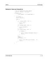
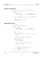


Obtaining Results from the Power-On Self-Test
Firmware
4 - 26
PPC/PMC-8260/DS1
Checksum
The checksum word contains the sum of all other POST result words. Before eval-
uating the POST results the software must calculate this checksum and verify it
against the checksum word. If the checksum does not match, no POST has been
executed.
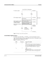
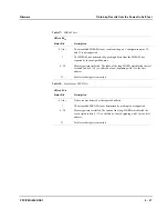
POST Progress Information
Provided that the PCR[INI] bit is set (see the “Controlling Boot Process” section on
page 4-13), the POST uses mailbox register 5 of the PowerSpan II (offset 464
16
) to
pass information to the host which test is currently being executed. In this context
this register is referred to as the test status register (TSR).
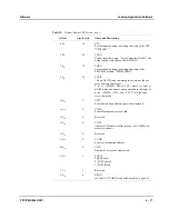
When a particular test is ongoing the corresponding bit as defined in table 16
“POST Result and Status Bits” on page 4-25 is set. All other bits are cleared. A val-
ue of zero indicates that the POST is either complete or a test has been completed
and the next test is about to be started.
The TSR can be used to monitor the progress of the POST and to see what the last
test was that has been executed in case of a fatal error.
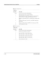
Device-Specific Results
More detailed information on the tests performed on each device are stored in the
test result words. Each bit set in one of these words indicates a specific operation
which failed.
In general, a test result word of FFFFFFFF
16
indicates a device that is either not as-
sembled or could not be accessed. Only the latter case is indicated as error in the
PRC.
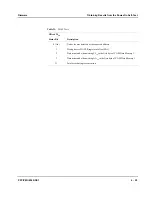
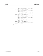
10
Set to 1 if the SDRAM passed all tests
11
Set to 1 if the SSRAM passed all tests
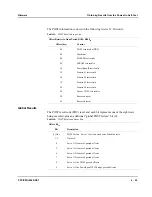
Table 16:
POST Result and Status Bits (cont.)
Offset: 00
16
Bit
Description
Summary of Contents for PPC/PMC-8260/DS1
Page 1: ...PPC PMC 8260 DS1 Reference Guide P N 6806800B10A July 2006 ...
Page 8: ...viii PPC PMC 8260 DS1 ...
Page 22: ...xxii PPC PMC 8260 DS1 ...
Page 26: ...xxvi PPC PMC 8260 DS1 ...
Page 30: ...xxx PPC PMC 8260 DS1 ...
Page 31: ...1 Introduction ...
Page 32: ......
Page 39: ...2 Installation ...
Page 40: ......
Page 53: ...3 Indicators and Connectors ...
Page 54: ......
Page 64: ...On Board Connectors Indicators and Connectors 3 12 PPC PMC 8260 DS1 ...
Page 65: ...4 Firmware ...
Page 66: ......
Page 104: ...Code Examples Firmware 4 40 PPC PMC 8260 DS1 ...
Page 105: ...5 Memory Map and Devices ...
Page 106: ......
Page 132: ...Resetting the Devices Memory Map and Devices 5 28 PPC PMC 8260 DS1 ...
Page 133: ...6 TDM Channel Configuration ...
Page 134: ......
Page 145: ...A Troubleshooting ...
Page 146: ......
Page 148: ...A 4 PPC PMC 8260 DS1 ...
Page 150: ...I 2 PPC PMC 8260 DS1 ...