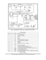
4. Verify voltage levels on all pins of the 10-pin connector prior to connecting the Oncore™ to the
RS-232 interface! See figure 1 for pin orientation.
5.
Remove power and connect the RS-232 interface to the Oncore™ receiver. Connect an appropriate
preamplified GPS antenna to the receiver.
IMPORTANT NOTE: Avoid placing the GPS antenna in close proximity to a laptop or PC.
This can cause interference with proper signal reception!
6.
Apply power to the interface and use VisualGPS software (
see Software Resources section
) to
initialize the Oncore™ receiver to NEMA mode and verify proper operation.
7.
Use NMEATime or similar software to verify clock synchronization.
The receiver must first be
initialized and changed to NEMA message output in order for NMEATime to work!
Diagnose further operational problems by verifying connections and signals with a voltmeter and
oscilloscope if required.
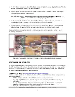
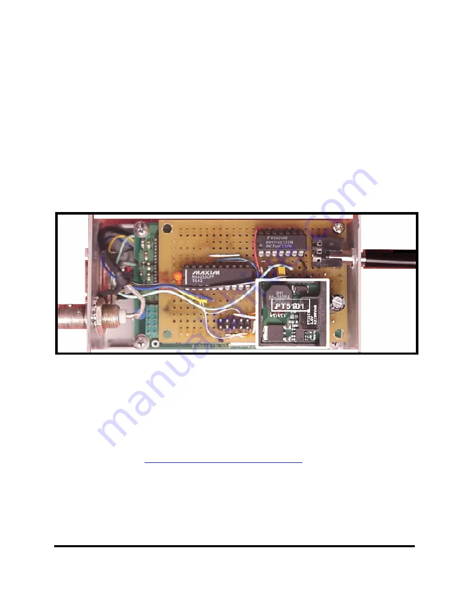
Figure 4 - Prototype RS232 & Clock PC Interface. Shown with optional switching regulator.
SOFTWARE RESOURCES
Many GPS applications found on the Internet utilize “NEMA” communications output protocol between
the GPS receiver and PC software. The ability to use this common protocol provides for a large number
of existing programs that can be utilized by this receiver
. We recommend you start your functional
verification and initial operations with VisualGPS.
VisualGPS (Freeware)
–
http://www.apollocom.com/VisualGPS/default.htm
This free program can be used to initialize the Oncore™ receiver to NEMA mode and verify operational
parameters. Includes:
•
NMEA Command Monitor - View NMEA sentences as they are received
•
Signal Quality/SNR Window - Satellite signal to noise ratios for all satellites are displayed
graphically.
•
Survey - Displays latitude, longitude and altitude graphically. Performs running statistical
analysis of location mean and least squares method with standard deviations.
•
Navigation - Monitor latitude, longitude and altitude.
QUICK-START GUIDE, MOTOROLA Oncore™ GT - GPS Module for Embedded OEM
5

