background image

5

— or —

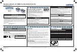
For radios with a Public Safety Speaker/Microphone (PSSM) and RF Adapter (RFA) 
installed

, loop the cord around the RFA and adjacent portion of the PSSM and then snap 

the latch back onto the strap (refer to Figure 2).

Figure 2 Radio with PSSM and RFA Installed

— or —

For charging a battery that is not attached to a radio

, loop the cord around the top of the 

battery, then snap the latch onto the snap on the top of the charger (refer to Figure 3).

Figure 3 Battery without Radio

6.

Before you remove a portable radio or battery from the vehicular charger, first unsnap the 
latch and unloop the cord from the secured radio or battery.

Cord

Latch

Strap

RAPID TRICKLE TEMP

VRS

OFF

RPTR

Summary of Contents for NTN9176 ASTRO XTS

Page 1: ...airbag inflates with great force DO NOT place objects including communication equipment in the area over the airbag or in the airbag deployment area If the communication equipment is improperly installed and the airbag inflates this could cause serious injury Installation of vehicle communication equipment should be performed by a professional installer technician qualified in the requirements for...

Page 2: ...ry to be maintained in a fully charged condition A radio can be operated while in the charger but this will prolong the amount of time needed to fully charge the battery NOTE Excessive use of a radio while it is in the charger will cause its battery to become discharged Battery No Type Description Battery No Type Description NTN8294_ NiCd Ultra High NTN8299_ NiMH Ultra High FM A B C D E G NTN8295_...

Page 3: ...Yellow Steady TEMP The battery is outside of its acceptable temperature range for rapid charging the battery will be charged at a reduced trickle rate when this occurs Allow the battery to warm or cool as appropriate The radio or battery may be left in the charger during this time if the temperature conditions inside the vehicle are appropriate and the charger will automatically switch to rapid ch...

Page 4: ...er strap that protrudes from the lower edge of the pocket opening the cord and the snappable leather latch The buttons on the latch and housing top are designed to mate with the snap on the strap 2 When the vehicular charger is not in use the latch may be snapped to the strap to stow it The unit is shipped from the factory in this configuration 3 To use the vehicular charger insert the portable ra...

Page 5: ... PSSM and RFA Installed or For charging a battery that is not attached to a radio loop the cord around the top of the battery then snap the latch onto the snap on the top of the charger refer to Figure 3 Figure 3 Battery without Radio 6 Before you remove a portable radio or battery from the vehicular charger first unsnap the latch and unloop the cord from the secured radio or battery Cord Latch St...

Page 6: ...utton If a battery alone is placed in the charger be sure that the slots on either side of the battery engage the two metal tabs at the bottom of the pocket near the four gold plated charger terminals When the battery is properly seated in the charger pocket the red LED will light steadily This indicates that the battery is being charged in the rapid charge mode Also if the radio and battery are i...

Page 7: ...existing holes occupied by vehicle wire harnesses Often there is an opportunity to route other cables using the same path Because of the wide variation in vehicle design these instructions may be modified to suit each particular installation A properly installed unit will minimize service calls and equipment downtime Consider the following guidelines when planning the installation DO consider a mo...

Page 8: ...or or operating controls DON T dress the cable over sharp edges that could cause wear or tearing of cable insulation DON T install the unit in a location where it may be difficult for the operator to reach DON T install the unit where it may interfere with the vehicle safety air bag deployment DON T install the unit where the LED indicators and switch may become physically damaged 2 Using the trun...

Page 9: ...se to a switched terminal on the vehicle s fuse box 9 Connect the black Gnd wire to any convenient vehicle ground 10 The white wire is for vehicular repeater operation only Please refer to installation instructions for the vehicular repeater for instructions on the connection of this wire 11 Carefully insert the connector on the end of the cable into the mating connector on the back of the charger...

Page 10: ...2 Repeater 3 N C 4 Switched fuse terminal ignition sense 5 N C 6 Vehicle ground AWG 18 20 20 18 Signal A PAC RT Ignition Sense Gnd Color Red White Yellow Black 1 2 3 4 5 6 Pin No Fuse 2A 250V Fuse 25A 250V Connector P 1 16 406 mm 36 914 mm Fuse Holder Inline Type Connector P1 Molex P N 03 09 1064 Pin 4 Pin 2 Pin 1 Pin 6 MAEPF 27085 O 21 533 mm ...

Page 11: ...sent of Motorola If repair or replacement under warranty becomes necessary the manufacturer s facility TPL Communications will serve as the repair depot Call to request a Return Authorization Number and return the product to the following address including a brief description of the problem a return address daytime telephone number and proof of purchase TPL Communications 3370 San Fernando Rd Unit...

Page 12: ... ASTRO are registered in the U S Patent and Trademark Office All other product or service names are the property of their respective owners Motorola Inc 2004 All rights reserved Printed in U S A Motorola Inc 8000 West Sunrise Boulevard Ft Lauderdale FL 33322 ...

Reviews: