background image

Motorola GmbH • Geschäftsbereich Funksysteme

.. - 1

<<

>>

I

IF Module

The IF module amplifies the 45 MHz signal from the mixer and provides the necessary channel
selection by the available crystal and ceramic filters. It supplies a demodulated AF signal to the
following AF-IC and provides the computer with an RSSI (received signal strength indicator) signal.

Power Supply (PS)

The power supply generates the necessary receiver voltage VRX. VRX is derived from the switched
battery  voltage  BATSWD  and  stabilised  at  8 V. VRX  is  switched  on  and  off  by  the  control  line
VTXCTRL.

3.2

Transmitter

Four  adjustment  values  for  four  power  stages  are  stored  in  the  radio  for  the  transmitter  output
stages in production. One of these values can be assigned to the “High Power” stage switchable by
the user, another to the “Low Power” stage with the help of WinIPP in the after-sales service. This
can be done uniformly for all channels or separately for each channel. To ensure as constant as
possible an output power over the whole frequency range, four times four setting values for 146
MHz, 155 MHz, 165 MHz and 174 MHz are determined in automatic adjustment.

The  switching  times  for  reception-transmission,  transmission-reception  mode  are  less  than  30
milliseconds. The power supplies for the transmitter are switched on and the T/R switch switched
to transmission mode via the control line VTXCTRL.

Transmitter Ouput Amplifier

The transmitter is available in three power ranges (1-6 W / 6-12 W / 12-25 W). The stored adjustment
values for the transmitter power in the MR radios are:

1-6 W:

1 W

2 W

6 W

6 W

6-12 W:

6 W

6 W

12 W

12 W

12-25 W:

12 W

12 W

25 W

25 W

The transmitter power of the MR 11 is keyed up with the aid of a D/A converter in the form of a
staircase  function  in  two  milliseconds. The  setting  values  are  passed  to  the  transmitter  via  the
control line VPWRREF after a linear interpolation.

3.3

Antenna Filter with Antenna Switch

The antenna filter connects either the receiver pre-stage or the transmitter output to the antenna
socket. Its transmission function has band pass character. Switching is effected by PIN diodes.

The MR 11 harmonic filter is a low pass.

2 - 4

MR 11

Summary of Contents for MR 11

Page 1: ... connections 2 Circuit diagrams 3 Spare parts 4 Assembly and conversion instructions 5 Service accessories 6 Programming with WinIPP 7 All rights reserved by Motorola GmbH Geschäftsbereich Funksysteme also for patent and trade mark applications Rights of disposal e g copyright and right of transfer to third parties are likewise held by us ...

Page 2: ...2 2 3 Circuit Description 2 3 3 1 Receiver 2 3 3 2 Transmitter 2 4 3 3 Antenna Filter with Antenna Switch 2 4 3 4 Frequency Conditioning 2 5 3 5 Analog Signal Processing 2 6 3 6 Unit Control 2 6 3 7 Signalling Module MDSR 134 2 7 4 Function of the External Connections 2 8 4 1 4 pin Rear Connection 2 8 4 2 10 pin FCC Plug 2 9 4 3 25 pin Socket Data Interface MR 11 R 2 9 2 1 MR 11 ...

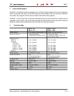
Page 3: ... With integrated keyboard and LCD With 25 pin data connection External connection 10 pin FCC socket 10 pin FCC socket loudspeaker and follower contact loudspeaker follower contact and 25 pin Sub D socket Frequency range MR 1116 146 174 MHz 146 174 MHz MR 1142 Receiver 400 440 MHz 400 440 MHz Transmitter Part A 1 6 W 400 420 MHz 400 420 MHz Part B 1 6 W 420 440 MHz 420 440 MHz Part C 10 25 W 400 42...

Page 4: ...ete receiver module consists of the VHF UHF pre stage RX a ring mixer the IF unit IF and a power supply PS Pre stage RX The pre stage is responsible for far off selectivity attenuation of the image frequency and the total sensitivity The circuit consists of two band pass filters and one amplifier in emitter circuit The pass range is divided into four reception ranges by two varicaps in the first b...

Page 5: ... output power over the whole frequency range four times four setting values for 146 MHz 155 MHz 165 MHz and 174 MHz are determined in automatic adjustment The switching times for reception transmission transmission reception mode are less than 30 milliseconds The power supplies for the transmitter are switched on and the T R switch switched to transmission mode via the control line VTXCTRL Transmi...

Page 6: ...he frequency of the free oscillating transmitter or receiverVCOs switching throughV352 controlled by port MFO1 of D362 by status word is divided down to a comparative frequency of 5 or 6 25 kHz with switchable dividers and compared with an identical high constant comparative frequency derived from the TCXO frequency of 12 8 MHz in a phase discriminator This supplies a control voltage dependent on ...

Page 7: ...sed for clock generation for other components provides the Chip Select signals of the memories has a port extension and analog and digital encoders decoders Microcontroller A 16 bit controller from Mitsubishi is used here Its designation is M37710 It is operated with approx 15 MHz This computer contains a 32 kB internal ROM The so called MELP SW Micro Electronic Processor Software needed for radio...

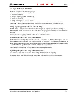
Page 8: ...wo separate tone signal generators allow use as a DTMF encoder Digital Signalling Function Scope of the MD 134 The MD 134 is an intelligent semiduplex modem It processes a 1200 b s FFSK signal The two frequencies are 1200 Hz for a logic 1 and 1800 Hz for a logic 0 The frame synchronisation is achieved by comparison with a synchronisation word in addition the inverse synchronisation word is searche...

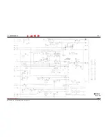
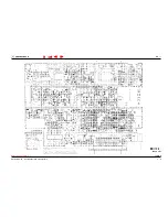
Page 9: ...on Please note The circuit diagrams and component mounting diagrams on the following pages are only for your information Work on the printed board is not planned in the service concept Violations will render guarantee claims invalid Spare parts cannot be delivered for unauthorized work on the printed board However work can be approved within a restricted scope in founded exceptional cases e g inst...

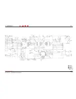
Page 10: ...Motorola GmbH Geschäftsbereich Funksysteme 1 I Refer to note on page 3 1 MR 1116 C MR 1116 R Basic unit Index 9 3 2 MR 11 ...

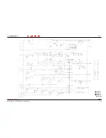
Page 11: ...Motorola GmbH Geschäftsbereich Funksysteme 1 I Refer to note on page 3 1 MR 1116 C MR 1116 R Basic unit Index 9 3 3 MR 11 ...

Page 12: ...Motorola GmbH Geschäftsbereich Funksysteme 1 I Refer to note on page 3 1 MR 1116 C MR 1116 R Basic unit Index 9 3 4 MR 11 ...

Page 13: ...Motorola GmbH Geschäftsbereich Funksysteme 1 I Refer to note on page 3 1 MR 1116 C MR 1116 R Basic unit Index 9 3 5 MR 11 ...

Page 14: ...Motorola GmbH Geschäftsbereich Funksysteme 1 I Refer to note on page 3 1 MR 1116 C MR 1116 R Basic unit Index 9 3 6 MR 11 ...

Page 15: ...Motorola GmbH Geschäftsbereich Funksysteme 1 I Refer to note on page 3 1 MR 1116 C MR 1116 R Basic unit Index 9 3 7 MR 11 ...

Page 16: ...Motorola GmbH Geschäftsbereich Funksysteme 1 I Refer to note on page 3 1 MR 1116 C MR 1116 R Basic unit Index 9 3 8 MR 11 ...

Page 17: ...Motorola GmbH Geschäftsbereich Funksysteme 1 I Refer to note on page 3 1 MR 1116 C MR 1116 R Basic unit Index 9 3 9 MR 11 ...

Page 18: ...Motorola GmbH Geschäftsbereich Funksysteme 1 I Refer to note on page 3 1 MR 1116 C MR 1116 R Basic unit Index 9 3 10 MR 11 ...

Page 19: ...Motorola GmbH Geschäftsbereich Funksysteme 1 I Refer to note on page 3 1 MR 1142 C MR 1142 R MR 1145 C MR 1145 R Basic unit Index 5 3 11 MR 11 ...

Page 20: ...Motorola GmbH Geschäftsbereich Funksysteme 1 I Refer to note on page 3 1 MR 1142 C MR 1142 R MR 1145 C MR 1145 R Basic unit Index 5 3 12 MR 11 ...

Page 21: ...Motorola GmbH Geschäftsbereich Funksysteme 1 I Refer to note on page 3 1 MR 1142 C MR 1142 R MR 1145 C MR 1145 R Basic unit Index 5 3 13 MR 11 ...

Page 22: ...Motorola GmbH Geschäftsbereich Funksysteme 1 I Refer to note on page 3 1 MR 1142 C MR 1142 R MR 1145 C MR 1145 R Basic unit Index 5 3 14 MR 11 ...

Page 23: ...Motorola GmbH Geschäftsbereich Funksysteme 1 I Refer to note on page 3 1 MR 1142 C MR 1142 R MR 1145 C MR 1145 R Basic unit Index 5 3 15 MR 11 ...

Reviews: