6809510A66-O
October 12, 2006
31
Level 1 and 2 Service Manual
Disassembly
6.
Remove the flex from the chassis.
7.
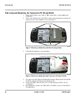
Left the keypad PC board away from the phone.
8.
To replace, align the flex connector the keypad PC board and gently press the
connector until properly seated in the connector socket.
9.
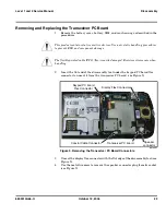
Thread the coaxial cable around the cable guide and seat the connector onto
its socket on the keypad PC board.
10. Insert and tighten the 2 T3 screws.
11. Paste on the silver chassis seal.
12. Reassemble the front housing, transceiver PC board, transceiver PC board
shield, antenna cap, SIM, battery and battery cover as described in the
procedures.
Removing and Replacing the Antenna
1.
Remove the battery cover, battery and SIM, as described in the procedures.
2.
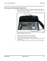
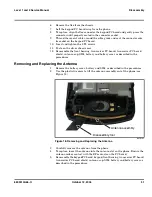
Use the plastic tweezers to lift the antenna assembly out of the phone (see
Figure 18).
3.
Carefully remove the antenna from the phone.
4.
To replace, insert the antenna into the antenna slot on the phone. Ensure the
antenna makes contact with the RF contacts on the PC board.
5.
Reassemble the keypad PC board, keypad, front housing, transceiver PC board,
transceiver PC board shield, antenna cap, SIM, battery and battery cover as
described in the procedures.
061618o
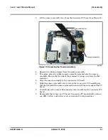
Figure 18. Removing and Replacing the Antenna
Antenn
a
ass
em
b
ly
Di
sass
em
b
ly tool
Summary of Contents for MOTOSLVR L72
Page 4: ...4 October 12 2006 6809510A66 O Contents MOTOSLVR L9 L72 ...
Page 49: ......

