Figure 43: Connectors on the Junction Box – Rear Panel
6
5
4
7
Connectors on the Junction Box - Rear Panel
4 = Auxillary PEI port
can be used with
PMKN4025_.
5 = 16 Pin Connector
for Accessories, uses
GMBN1021_ or full kit
HLN9457_ Accessory
connector kit.
6 = Connector for
connecting a laptop
via RS232 cable
7 = TELCO-connector
for fist microphone
(GMMN4063_)
4.6.8
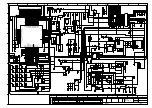
Connection Plan for the Junction Box Accessory Terminal
Figure 44: Connection Plan for the Speaker
1
2
3
4
5
6
7
1
2
1
2
Number
Description
1
Junction Box Terminal
2
Speaker
68015000181-LB
Chapter 4: Radio Installation
84
Summary of Contents for Malux MTM5400 Series
Page 2: ......
Page 4: ...This page intentionally left blank ...
Page 8: ...This page intentionally left blank ...
Page 12: ...This page intentionally left blank ...
Page 15: ...Table 73 Fuse Identification 133 68015000181 LB List of Tables Send Feedback 15 ...
Page 16: ...This page intentionally left blank ...
Page 18: ...This page intentionally left blank ...
Page 22: ...This page intentionally left blank ...
Page 128: ...This page intentionally left blank ...


