background image

IMPORTANT SAFETY INSTRUCTIONS 

2 3  

Battery usage 
Notwithstanding any information provided by Motorola in this manual regarding the use of 
batteries, the end user assumes all responsibility and liability to use and dispose of batteries in 
accordance with all applicable laws, rules and regulations. Motorola will not be liable to anyone for 
the end user's failure to use and/or dispose of batteries in the proper manner and in accordance 
with such laws, rules and regulations, or for any defect contained in batteries which may cause 
injury damage to persons or property. 

2 4  

Heat 
This product should be situated away from heat sources such as radiators, heat registers, stoves, 
or other products (including amplifiers) that produce heat. 

Regulatory Information 

Federal Communications Commission Radio and Television Interface Statement for a Class ‘B’ 
Device 

This equipment has been tested and found to comply with the limits for a Class B digital device, 
pursuant to part 15 of the FCC Rules. These limits are designed to provide reasonable protection 
against harmful interference in the residential installation. This equipment generates, uses and can 
radiate radio frequency energy and, if not installed and used in accordance with the instructions, may 
cause harmful interference to radio communications. However, there is no guarantee that interference 
will not occur in a particular installation. 

If the equipment does cause harmful interference to radio or television reception, which can be 
determined by turning the equipment off and on, the user is encouraged to try to correct the interference 
by one of the following measures: 

• 

Increase the separation between the equipment and the affected receiver 

• 

Connect the equipment on a circuit different from the one the receiver is on 

• 

Ensure that the cover plate for the security card is secured and tight 

Changes or modification not expressly approved by the party responsible for compliance could void the 
user’s authority to operate the equipment. 

Declaration of Conformity 

According to 47 CFR, Parts 2 and 15 for Class B Personal Computers and Peripherals; and/or CPU 
Boards and Power Supplies used with Class B Personal Computers, Motorola, Inc., 6450 Sequence 
Drive, San Diego, CA 92121, 1-800-225-9446, declares under sole responsibility that the product 
identifies with 47 CFR Part 2 and 15 of the FCC Rules as a Class B digital device. Each product 
marketed is identical to the representative unit tested and found to be compliant with the standards. 
Records maintained continue to reflect the equipment being produced can be expected to be within the 
variation accepted, due to quantity production and testing on a statistical basis as required by 47 CFR 
2.909. Operation is subject to the following condition: This device must accept any interference received, 
including interference that may cause undesired operation. The above named party is responsible for 
ensuring that the equipment complies with the standards of 47 CFR, Paragraphs 15.101 to 15.109. The 
Class B digital apparatus meets all requirements of the Canadian Interface Causing Equipment 
Regulations. 

Summary of Contents for DCT6400 Series

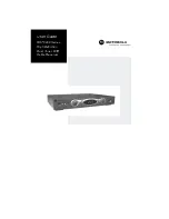
Page 1: ...OPTION GUIDE POWER MENU MSGS RECORD ON REMOTE INFO SELECT User Guide DCT6400 Series High Definition Dual Tuner DVR Cable Receiver ...

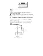
Page 2: ...a risk of electric shock to persons The exclamation point within an equilateral triangle is intended to alert the user to the presence of important operating and maintenance servicing instructions in the literature accompanying the appliance REPAIRS If you find the unit in need of repair call Motorola Support at 1 866 668 2271 or 1 866 MOT BCS1 NOTE TO CATV SYSTEM INSTALLER This reminder is provid...

Page 3: ...acing the product on a bed sofa rug or similar surface Equipment should never be placed near or over a radiator or heat register or in a built in installation such as a bookcase or rack unless proper ventilation is provided 10 Power sources This product should be operated only from the type of power sources indicated on the marking label If you are not sure of the type of power supplied to your ho...

Page 4: ...attempt to service this equipment yourself as opening or removing covers may expose you to dangerous voltage or other hazards refer all servicing to qualified service personnel 20 Damage requiring service Unplug this equipment from the wall outlet and refer servicing to qualified service personnel under the following conditions When the power supply cord or plug is damaged Ä If the equipment has b...

Page 5: ...elevision reception which can be determined by turning the equipment off and on the user is encouraged to try to correct the interference by one of the following measures Increase the separation between the equipment and the affected receiver Connect the equipment on a circuit different from the one the receiver is on Ensure that the cover plate for the security card is secured and tight Changes o...

Page 6: ...opy or translate the User Guide included with the Software other than for personal use 3 Copy alter translate decompile disassemble or reverse engineer the Software including but not limited to modifying the Software to make it operate on non compatible hardware 4 Remove alter or cause not to be displayed any copyright notices or startup message contained in the Software programs or documentation ...

Page 7: ...____________________________________________ Copyright 2004 Motorola Inc All rights reserved No part of this publication may be reproduced in any form or by any means or used to make any derivative work such as translation transformation or adaptation without written permission from Motorola Inc Motorola reserves the right to revise this publication and to make changes in content from time to time...

Page 8: ...T For High Definition TV 9 User Settings 11 On Screen Graphics 14 Connecting Your DCT 15 Video Options 16 Important Safety Considerations 17 Connecting Your DCT to a HDTV Video Only 18 Connecting Your DCT to a HDTV Audio Only 20 Connecting Your DCT to an A V Receiver Audio Only 22 Connecting Your DCT to a Stereo TV 24 Connecting Your DCT to a Stereo TV and Stereo VCR 26 Connecting Your DCT to an A...

Page 9: ...2 Recording Your Connections 30 Data Devices 31 Data Features 31 Troubleshooting 32 ...

Page 10: ...erfaces The DCT is fully equipped with a factory installed hard drive for hours of DVR functionality which includes the capability of recording high definition HD programs and watch and record functionality This User Guide introduces you to the basic features of the DCT outlines important safeguards and provides several options for integrating this component into your current entertainment system ...

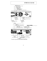
Page 11: ...ce USB USB DVI ETHERNET Connects to support devices Connects to support devices Connects DCT to a high definition TV Supports PC networking CABLE IN Connects to cable signal from your service provider IR Enables DCT to control a VCR while recording a selected program Not supported by all program guides INFO MENU POWER CURSOR MSGS ON USB VIDEO IN L AUDIO IN R CURSOR Moves cursor around program guid...

Page 12: ...order or other video device Delivers video to an external device such as a TV or VCR Y Pb Pr Delivers component video S Video Connect to S Video input of TV or VCR OPTICAL SPDIF Provides Dolby Digital 5 1 audio or PCM audio IEEE 1394 Connects to audio and video devices AC Switched Outlet Connect AC power cord from another device such as a TV or VCR OPTION GUIDE SELECT CHANNEL SMART CARD REMOTE REC...

Page 13: ... or on the remote control to adjust the volume When you adjust the volume the volume scale is displayed on the screen Press MUTE on the remote control to turn the sound off and on again For best audio quality use the remote control to set the DCT to approximately of the maximum volume level and then adjust the audio levels on external devices such as your TV or A V Receiver Interactive Program Gui...

Page 14: ...roviding trick playback modes pause fast forward slow forward fast rewind slow rewind You may experience a slight delay between time shifted and live TV With the DCT you can Record Programming Record hours of TV programming The total hours of recorded content will vary based on the storage capacity of your DCT and type of content digital analog or HD being recorded Maintain a Personal Program Libr...

Page 15: ...els at the same time Simultaneously Record Two Shows and Watch a Recorded Program Watch a program recorded on your DCT while recording up to two other programs at the same time You can also easily switch viewing the pre recorded program and either of the programs you re recording ...

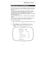
Page 16: ...lay to set your DCT to automatically optimize both standard and HD video based on your HDTV and personal preferences If you use the IEEE 1394 connector no adjustments to your settings are required You can use your on screen menu to configure your HD settings for TV type DVI and or Y Pb Pr video output and closed captioning To access your HD settings 1 Ensure that your DCT is plugged into a power o...

Page 17: ...and save your settings press the POWER or MENU key The HD settings are described in the table on the following pages The DVI YPbPr OUTPUT setting is displayed as YPbPr OUTPUT if you are not using the DVI video connection The user settings will also be displayed on the front panel LED whether your TV is off or on If the on screen display menu does not appear on your HDTV screen your TV may not supp...

Page 18: ... widescreen programming DVI YPbPr Output Sets the video display format for the component video outputs The LED panel displays the format you select Defaults to 1080i Options are 1080i 720p 480p or 480i Some TVs only support certain display formats Check your TV user manual for more information If you are not using an HDTV with the DCT selecting a format other than 480i causes the on screen display...

Page 19: ...nnot display 480p format on their component video inputs Y Pb Pr Check the TV user manual for more information Graphics overlaying the video are not displayed Stretch automatically stretches all standard definition programming to fill your widescreen display Stretch can only be selected if you have TV Type set to 16 9 Closed Caption Turns closed captions off or on The LED panel displays the status...

Page 20: ...losed captions Defaults to AUTO Options are AUTO TRANSPARENT TRANSLUCENT SOLID or FLASHING Service Selection Sets the service for closed captions Defaults to AUTO Options are AUTO PRIMARY LANGUAGE SECONDARY LANGUAGE 3 4 5 or 6 Settings Sets the default settings for closed captions AUTO or the settings you have configured USER Defaults to AUTO Options are AUTO or USER Restore Defaults Resets the on...

Page 21: ...ough a program grid On screen graphics are not available on all DCT Y Pb Pr output setting and video output combinations On screen graphics are always available if your DCT is connected through the HD outputs DVI or Y Pb Pr Standard definition connections S Video or composite Video will only display on screen graphics if the YPbPr Output is set to 480i On screen graphics will not be displayed when...

Page 22: ...00 Series of High Definition Cable Receivers the DCT6408 DCT6412 and DCT6416 Before you move or change components on your entertainment system review the following For basic cable connections use 75 ohm coaxial cables equipped with F type connectors Disconnect power from the DCT before connecting or changing cable connections For information on connecting for HDTV see Video Options on the next pag...

Page 23: ... component video connections are not available on your TV use the S Video connection Video also referred to as composite video SDTV If S Video is not available use the composite video VIDEO connection RF Input SDTV If your TV only has an RF input you can connect to the DCT using a RF Modulator which can be purchased at most electronics stores DVI or IEEE 1394 HDTV and SDTV DVI and IEEE 1394 offer ...

Page 24: ...all sides Do not block the slots and openings in the DCT Do not place anything on top of the DCT Do not position the DCT in an enclosed space that would restrict airflow around the unit Do not position the DCT near any external heat source that could raise the temperature around the unit Do not place the DCT on top of another heat producing electronic device Allow for adequate ventilation around t...

Page 25: ... Video Input Y Pb Pr DVI HDTV IEEE 1394 DCT6400 Series AUDIO OUT AUDIO IN VIDEO IN L OUT S VIDEO IEEE 1394 OPTICAL SPDIF SPDIF Y Pb Pr IEEE 1394 connection HDTV Component video connection TV Pass Card R ETHERNET USB IR DVI D OUT CABLE IN DVI connection Either or Cable in ...

Page 26: ...DCT for High Definition TV IEEE 1394 If your HDTV has an IEEE 1394 connector you can use the IEEE 1394 for both your video and audio connection connect an IEEE 1394 cable to the IEEE 1394 IEEE 1394 connectors on your HDTV and DCT On screen graphics will not be displayed when you are using the IEEE 1394 connection on the rear panel of the DCT DVI If your TV has a DVI input use the DVI connection fo...

Page 27: ...O OUT AUDIO IN TV Pass Card VIDEO R IN L OUT S VIDEO IEEE 1394 OPTICAL SPDIF SPDIF Y Pb Pr ETHERNET USB IR DVI D OUT CABLE IN DCT6400 Series CABLE ANTENNA IN OPTICAL SPDIF INPUT AUDIO LEFT AUDIO RIGHT HDTV Audio connection Optical connection Optional ...

Page 28: ...rs on the HDTV If your equipment supports it The optical OPTICAL SPDIF or coaxial digital SPDIF audio outputs may be used in place of the stereo audio outputs AUDIO R and L In most cases these outputs offer a higher level of audio quality including support for 5 1 Surround Sound For information on configuring your DCT settings see Optimizing Your DCT for High Definition TV ...

Page 29: ...L OUT S VIDEO IEEE1394 OPTICAL SPDIF SPDIF Y Pb Pr ETHERNET USB IR DVI D OUT CABLE IN DCT6400 Series DIGITAL INPUT TV MONITOR OUTPUT SPEAKER CONNECTORS COAX VIDEO S VIDEO R DVD CABLE TV VIDEO 2 IN OUT VCR AUDIO VIDEO L VIDEO S VIDEO OPTICAL Audio connection Optical connection Digital audio connection Either or ...

Page 30: ...fer a higher level of audio quality including support for 5 1 surround sound Optical SPDIF Connect the optical SPDIF cable to the OPTICAL SPDIF connector on the DCT and the OPTICAL connector on the A V receiver SPDIF Connect the digital audio cable to the SPDIF connector on the DCT and the DIGITAL INPUT COAX connector on the A V receiver Stereo audio Connect the stereo audio cable to the AUDIO R a...

Page 31: ... IN L OUT S VIDEO IEEE 1394 OPTICAL SPDIF SPDIF Y Pb Pr ETHERNET USB IR DVI D OUT CABLE IN DCT6400 Series CABLE ANTENNA IN INPUT S VIDEO VIDEO AUDIO LEFT AUDIO RIGHT Stereo TV Either or Either or RF 75 ohm connection Video connection S Video connection Audio connection Cable in ...

Page 32: ...UDIO R and L connectors on the DCT and the AUDIO LEFT and AUDIO RIGHT connectors on the stereo TV Connect a video cable to the VIDEO OUT connector on the DCT and the INPUT VIDEO on the TV or an S video cable to the S VIDEO connectors on the DCT and the TV This video connection method does not support HD video For more information see Connecting your DCT to an HDTV Video Only on page 18 ...

Page 33: ...VIDEO IEEE 1394 OPTICAL SPDIF SPDIF Y Pb Pr ETHERNET USB IR DVI D OUT CABLE IN DCT6400 Series To TV CABLE ANTENNA IN INPUT AUDIO L R VIDEO OUTPUT AUDIO L R VIDEO CABLE ANTENNA IN INPUT S VIDEO VIDEO AUDIO LEFT AUDIO RIGHT Stereo TV Stereo VCR RF 75 ohm connection Video connection Audio connection Cable in ...

Page 34: ...ct a video cable to the VIDEO OUT connector on the DCT and the INPUT VIDEO connector on the stereo VCR 4 Connect a stereo audio cable to the OUTPUT AUDIO R and L connectors on the Stereo VCR and the INPUT AUDIO RIGHT and LEFT connectors on the stereo TV 5 Connect a video cable to the OUTPUT VIDEO connector on the stereo VCR and the INPUT VIDEO connector on the stereo TV The video connection method...

Page 35: ...ITAL INPUT TV MONITOR OUTPUT SPEAKER CONNECTORS COAX VIDEO S VIDEO R DVD CABLE TV VIDEO 2 IN OUT VCR AUDIO VIDEO L VIDEO S VIDEO OPTICAL CABLE ANTENNA IN INPUT S VIDEO VIDEO AUDIO LEFT AUDIO RIGHT To TV CABLE ANTENNA IN INPUT AUDIO L R VIDEO OUTPUT AUDIO L R VIDEO Stereo VCR A V receiver Stereo TV RF 75 ohm connection Video connection Audio connection Optical connection Digital audio connection ...

Page 36: ... cable to the INPUT VIDEO connector on the stereo VCR and the VIDEO VCR OUT connector on the A V receiver 7 Connect a video cable to the OUTPUT VIDEO connector on the stereo VCR and the VIDEO VCR IN connector on the A V receiver 8 Connect a video cable to the INPUT VIDEO connector on the stereo TV and the TV MONITOR OUTPUT video connector on the A V receiver If your equipment supports it The optic...

Page 37: ...IDEO VIDEO OUT To TV CABLE ANTENNA IN INPUT AUDIO L R VIDEO OUTPUT AUDIO L R VIDEO DCT6400 Series AUDIO OUT AUDIO IN TV Pass Card VIDEO PRINTER R IN L OUT S VIDEO IEEE 1394 OPTICAL SPDIF SPDIF Y Pb Pr ETHERNET USB IR DVI DOUT CABLE IN VCR DIGITAL INPUT TV MONITOR OUTPUT SPEAKER CONNECTORS COAX VIDEO S VIDEO R DVD CABLE TV VIDEO 2 IN OUT VCR AUDIO VIDEO L VIDEO S VIDEO OPTICAL A V receiver DVD IN O...

Page 38: ... contacting your service provider Advanced data features require the proper application and network infrastructure to operate Data Features In addition to high quality audio and video the DCT has the capability to deliver high speed data services such as Internet access e mail IP Telephony E Commerce and home banking Your DCT may be equipped with the interface connections illustrated but their fun...

Page 39: ...emote control may be depleted The DCT may have received a software update and may not power on while the new software is being installed Try again in a few minutes The remote control does not work Verify that the remote control is in Cable mode Verify that there are no obstructions between the remote control and the DCT Aim the remote control directly at the DCT front panel not the TV or VCR The a...

Page 40: ...hat you have the correct cables for the audio ports Verify that the audio cables are firmly connected between the DCT and the audio playback device TV receiver DVD player etc There is no audio from the center and or surround speakers of a home theater receiver connected to the DCT Not all Dolby Digital programs feature full 5 1 surround sound In some cases the programs may only contain left and ri...

Page 41: ...er Settings menu and cycle through the available output formats until a picture displays on the TV Verify that all video cables between the DCT and the TV are firmly connected There are no graphics closed captions or program guides appearing on the TV screen The DCT cannot generate graphics on all video outputs at all times If the DCT is set to 1080i 720p or 480p output format graphics are only av...

Page 42: ...These programs are broadcast in 16 9 HD formats even though the video is not 16 9 There are black bars above and below the picture All 4 3 HDTVs display HD programs in letterbox format black bars above and below the picture because of the shape of the display screen Turn on the 4 3 OVERRIDE feature in the User Settings menu This enables most standard screen TVs to display a full screen picture whe...

Page 43: ...dcaster You can minimize this by activating the zoom feature on the TV A broadcaster may include black bars on either side of a wide screen broadcast This is called a hybrid aspect ratio and results in a black border surrounding the video on a 4 3 TV Because this is part of the broadcast the DCT cannot correct the video You may be able to minimize the border using the zoom feature on the TV The DC...

Reviews: