Performing Installation Tasks
526359-001
MGBI
2-25
Port LEDs are grouped vertically. A number above each LED group indicates the
channel number associated with the group. The single downstream channel is
numbered
0
and the four upstream channels are numbered
0
,
1
,
2
, and
3
describes the possible display states of these LEDs during operation.
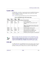
Network LEDs
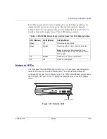
The front panel Network LEDs, shown in
, are green, and illuminate to
indicate the state of each of the Ethernet ports. The LEDs labeled
0
through
3
correspond to the four 10/100 Ethernet ports. The LEDs labeled
4
and
5
correspond to
the two Gig-E SFP ports.
provides an interpretation of the LED display
states.
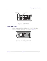
Figure 2-19 Network LEDs
Table 2-3 BSR 2000 Downstream and Upstream Port LED Display States
STS (Status)
ALM (Alarm)
Interpretation
Green
Off
Normal operating status.
Green
Amber
Operating with an alarm condition detected.
Note:
An alarm condition detected for an
individual port also causes the System Alarm
LED to light.
Off
Amber
Failed port. Port is not operational.
Off
Off
Port is not configured.
STS
DOWNSTREAM
UPSTREAM
NETWORK
ALM
0
1
1
0
2
3
2
3
5
4
0
SYSTEM
PWR
FAIL STS ALM
RED
bsr2k042
Network LEDs


