Performing Installation Tasks
526359-001
MGBI
2-23
System LEDs
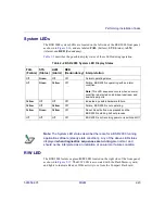
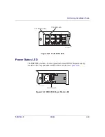
The BSR 2000 system LEDs are located on the left side of the BSR 2000 front panel,
as shown in
, and are labeled
FAIL
(Failure),
STS
(Status),
ALM
(Alarm), and
RED
(Redundancy).
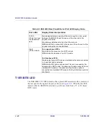
describes the possible display states of these LEDs during operation.
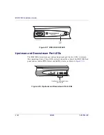
R/W LED
The BSR 2000 features a green
R/W
LED located on the right side of the front panel,
. The R/W LED is associated with the Flash Memory card,
and lights to indicate Read or Write activity to or from the Compact Flash card.
Table 2-2 BSR 2000 System LED Display States
FAIL
(Failure)
STS
(Status)
ALM
(Alarm)
RED
(Redundancy) Interpretation
Off
Green
Off
Off
Normal operating status.
Off
Green
Yellow
Off
Failure. BSR 2000 is operating with an alarm
condition.
Note:
This LED sequence occurs when an alarm
condition is detected on individual upstream and
downstream ports.
Yellow
Off
Off
Off
Indicates a possible hardware failure.
Yellow
Off
Yellow
Off
Failure. BSR 2000 is not operating.
Yellow
Green
Yellow
Off
Reset. Reset button was pressed and the
BSR 2000 is starting its boot process.
Off
Off
Off
Off
BSR 2000 is not receiving power or is switched Off.
Note:
The System LED states described here are for a BSR 2000 running
application software (steady state condition). Any of the above LED states
displayed
when diagnostics sequences are running
are normal, and
should not be interpreted as an indication of an alarm or failure condition.

