Motorola Avigilon 2.0C-H5A-B1 Installation Manual Download Page 19

Resetting to Factory Default Settings

If the device no longer functions as expected, you can choose to reset the device to its factory default
settings.

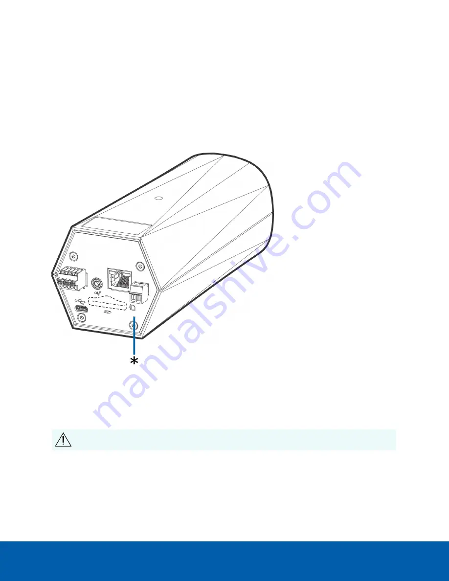
Use the firmware revert button to reset the device. The firmware revert button is shown in the following
diagram:

For models that feature a microSD card slot, resetting the camera will not affect video that has been
recorded to the microSD card.

Figure 2:

The firmware revert button on the rear of the camera

1. Ensure the device is powered on.

2. Using a straightened paperclip or similar tool, gently press and hold the firmware revert button.

3. Release the button after three seconds.

CAUTION —

Do not apply excessive force. Inserting the tool too far may damage the camera.

Resetting to Factory Default Settings

13

Summary of Contents for Avigilon 2.0C-H5A-B1

Page 1: ...Installation Guide Avigilon H5A Box Camera Models 2 0C H5A B1 2 0C H5A B2 2 0C H5A B3 4 0C H5A B2 4 0C H5A B3 6 0C H5A B2 8 0C H5A B2 ...

Page 2: ...nt or other intellectual property rights of Avigilon Corporation or its licensors Disclaimer This document has been compiled and published using product descriptions and specifications available at the time of publication The contents of this document and the specifications of the products discussed herein are subject to change without notice Avigilon Corporation reserves the right to make any suc...

Page 3: ... This product is intended to be supplied by a UL Listed Power Unit marked Class 2 or LPS or Limited Power Source with output rated 12 VDC or 24 VAC 7 W min or Power over Ethernet PoE rated 48 VDC 7 W min l Any external power supply connected to this product may only be connected to another Avigilon product of the same model series External power connections must be properly insulated l Do not conn...

Page 4: ...g 1 6 lb weight l Use of controls or adjustments or performance of procedures other than those specified in this document may result in hazardous radiation exposure l If used outdoors an approved outdoor mounting adapter or enclosure is required Consult with Avigilon for more information iv ...

Page 5: ...e or more of the following measures l Reorient or relocate the receiving antenna l Increase the separation between the equipment and the receiver l Connect the equipment into an outlet on a circuit different from that to which the receiver is connected l Consult the dealer or an experienced radio TV technician for help Changes or modifications made to this equipment not expressly approved by Avigi...

Page 6: ...ng an IP Address 6 Accessing the Live Video Stream 7 Aiming and Focusing the Camera 7 Optional Configuring SD Card Storage 8 Configuring the Camera 8 For More Information 8 Cable Connections 9 Connecting External Power 9 Connecting to External Devices 9 Connecting to Microphones Speakers and Video Monitors 10 Connection Status LED Indicator 12 Resetting to Factory Default Settings 13 Setting the I...

Page 7: ...nts Provides mounting points for the camera Mounts accept 1 4 20 x 5 16 max thread UNC bolts commonly found on tripods and mounting brackets 2 Serial number tag Device information product serial number and part number label Overview 1 ...

Page 8: ... indicator Indicates if there is an active connection in the Ethernet port 5 Ethernet port Accepts an Ethernet connection to a network Server communication and image data transmission occurs over this connection Also receives power when it is connected to a network that provides Power over Ethernet 6 Power connector block Accepts a terminal block with either an AC or DC power connection DC input c...

Page 9: ...Accepts an SD card for onboard storage 8 Micro USB port Accepts a micro USB to USB adapter Only required when using the Avigilon USB Wi Fi Adapter Rear View 3 ...

Page 10: ...with the bracket enclosure or tripod for detailed mounting instructions WARNING Use only UL listed mounting bracket suitable for the mounting surface and minimum 0 7 kg 1 6 lb weight Connecting Cables Refer to the diagrams in the Overview section for the location of the different connectors To connect the cables required for proper operation complete the following 1 If external input or output dev...

Page 11: ...e first user For more information see the Avigilon High Definition H4 and H5 IP Camera Web Interface User Guide l Camera Configuration Tool version 1 4 4 or later cameras discovered in the factory default state will be identified by Select the Admin Users tab to create the first user For more information see the Avigilon Camera Configuration Tool User Guide l USB Wi Fi Adapter when connecting a ca...

Page 12: ...it is connected to a network Note If the device cannot obtain an IP address from a DHCP server it will use Zero Configuration Networking Zeroconf to choose an IP address When set using Zeroconf the IP address is in the 169 254 0 0 16 subnet The IP address settings can be changed using one of the following methods l The mobile web interface using the USB Wifi Adapter For more information see Option...

Page 13: ...ing on the manufacture date of your camera you will have one of the two options below to log in for the first time l Cameras manufactured after January 1 2020 these cameras do not have a default username or password and will be in a factory default state You must create a user with administrator privileges before the camera is operational For more information see Initializing a Camera Username and...

Page 14: ... User Guide l If you have installed multiple cameras you can use the Avigilon Camera Configuration Tool to configure common settings For more information see the Avigilon Camera Configuration Tool User Guide l If the camera is connected to the Avigilon Control Center system you can use the client software to configure the camera For more information see the Avigilon Control Center Client User Guid...

Page 15: ...k or damage the wires 3 Insert the two power wires into the two terminals on the power connector block The connection can be made with either polarity Use a small slotted 5 64 or 2 mm blade width screwdriver to loosen and tighten the terminals 4 Attach the power connector block back into the camera WARNING This product is intended to be supplied by a UL Listed Power Unit marked Class 2 or LPS or L...

Page 16: ... 485 pin for controlling external equipment 5 RS 485 B Inverting RS 485 pin for controlling external equipment l 0 External Device l Relay l Switch Connecting to Microphones Speakers and Video Monitors The camera can be connected to an external microphone speaker and video monitor through the mini jack 3 5 mm audio video connector Avigilon part number CM AC AVIO1 Only the 2 0 megapixel models can ...

Page 17: ... the flicker control is set to 50 Hz the video output signal is PAL Use the Camera Installation Tool to configure the camera s flicker control in the Image and Display setup The pinout for the connector is shown in the following diagram The wiring for the connector pinout is shown in the following table Pin Purpose Wire 1 Audio IN Red 2 Composite Video OUT Black 3 GND Yellow 4 Audio OUT Green Conn...

Page 18: ...tempting to obtain an IP address Discoverable Two short flashes every second Obtained an IP address but not connected to the Network Video Management software Upgrading Firmware Two short flashes and one long flash every second Updating the firmware Connected On Connected to the Network Video Management software or an ACC Server The default connected setting can be changed to Off using the camera ...

Page 19: ...at feature a microSD card slot resetting the camera will not affect video that has been recorded to the microSD card Figure 2 The firmware revert button on the rear of the camera 1 Ensure the device is powered on 2 Using a straightened paperclip or similar tool gently press and hold the firmware revert button 3 Release the button after three seconds CAUTION Do not apply excessive force Inserting t...

Page 20: ...n H4 and H5 IP Camera Web Interface User Guide 1 Locate and make note of the MAC Address MAC listed on the Serial Number Tag for reference 2 Open a Command Prompt window and enter the following commands a arp s New Camera IP Address Camera MAC Address For example arp s 192 168 1 10 00 18 85 12 45 78 b ping l 123 t New Camera IP Address For example ping l 123 t 192 168 1 10 3 Reboot the camera 4 Cl...

Page 21: ... Avigilon warranty terms for this product are provided at avigilon com warranty Warranty service and technical support can be obtained by contacting Avigilon Technical Support avigilon com contact us Limited Warranty and TechnicalSupport 15 ...

Reviews: