May 28, 2008
6871620L01-C
3-28
VOCON Section
3.2.6
Radio Power-Up/Power-Down Sequence
The radio power up sequence begins with pressing the Power On button on the keypad. When the
button is pressed, the mechanical switch MECH_SW pin will be pulled low. If "MECH_SW = "0", and
BAT_7V5 pin is above the "Power Up Threshold", then MAKO IC will pull the FET_ENX pin to
GROUND, thus driving the gate of external P-MOSFET to low, enabling the P-MOSFETs (Q1301
and Q1302) to supply power to the MAKO IC as well as the RF transceiver section (
supplies B+ to the VOCON section, SW_B+ and RF transceiver section, ).
With SW_B+ enabled, the VSW1 switched regulator will be ready and subsequently, other MAKO
regulators such as V1.875, V1.55, V2 and VCC5 are sequentially enabled and provide power to all
MAKO internal blocks and external systems including the microprocessor (Patriot), memory ICs and
radio RF circuits. The RESETX pin is asserted low for an additional 32ms once all DC regulators are
stable. It is then de-asserted, allowing the microprocessor to start.
In order to power-down the radio, the ON/OFF button has to be pressed for a specified
(programmable) duration (default setting set to 3 seconds). The ON/OFF circuitry will then pull
MECH_SW to high (MECH_SW = 1) and the MAKO IC starts an internal 125ms watchdog timer and
sets the shutdown interrupt flag which causes the INT_X interrupt output pin to assert low. The
microprocessor then determines (via SPI register access) that it must initiate the power-down
sequence. The watchdog timer will be refresh by the microprocessor via SPI to prevent it from timing
out. Upon expiration of the watch dog timer, MAKO will assert RESETX to turn-off all DC regulators
and de-asserts the FET_ENX pin which removes the SW_B+ and supplies, thus killing all
power to the radio.
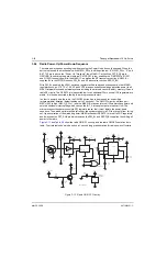
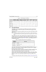
show the radio ON/OFF circuitry and the radio ON/OFF operation truth
table. The truth table shown is based on a 3 second long press duration for radio power-off criteria.
Figure 3-12. Radio ON/OFF Circuitry
R1
R2
V2_FIL
R9922
1K
Q9906
ON_OFF_det
ON_OFF
5V_Misc
5V_Misc
5V_Misc
5V_Misc
5V_Misc
R9923
10K
C9953
0.10uF
0.10uF
0.10uF
0.10uF
0.10uF
0.10uF
0.10uF
Inverter
C9952
R9960
0
C9951
MECH_SW
D Flip-flop
C9969
C9954
U9918-1
U9918-2
C9980
Q9905
R9925
R9924
10K
10K
Patriot_ONOFF
R9926
1K
ON/OFF Circuitry
GPIO
1
2
4
OR Gate
U9902
U9901
GND
VCC
4
1
1
2
2
3
4
3
5
GND
VCC
GND
VCC
GND
VCC
OUTY
INB
INA
R9927
30K
PR
D
CP
CLR
U9903
Q
Q‘
5
3
4
6
1
2
7
8
5
3
PWR_GND
AND Gate
Summary of Contents for ASTRO XTSTM 4000
Page 1: ...COLOR CHORDS 7 ASTRO XTSTM 4000 Portable Radio Detailed Service Manual ...
Page 2: ......
Page 16: ...May 28 2008 6871620L01 C xiv Commercial Warranty Notes ...
Page 22: ...May 28 2008 6871620L01 C 1 6 Introduction Notes ...
Page 26: ...May 28 2008 6871620L01 C 2 4 Radio Power Notes ...
Page 56: ...May 28 2008 6871620L01 C 3 30 Theory of Operation Notes ...
Page 100: ...May 28 2008 6871620L01 C 6 8 Troubleshooting Waveforms Notes ...
Page 194: ...May 28 2008 6871620L01 C B 2 Motorola Service Centers Notes ...
Page 204: ...May 28 2008 6871620L01 C Glossary 10 Glossary Notes ...
Page 209: ......

