6871620L01-C
May 28, 2008
VOCON Section
3-23
3.2.4.3.1 Radio CE Connector and Option Selects
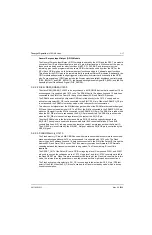
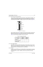
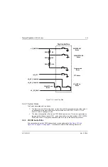
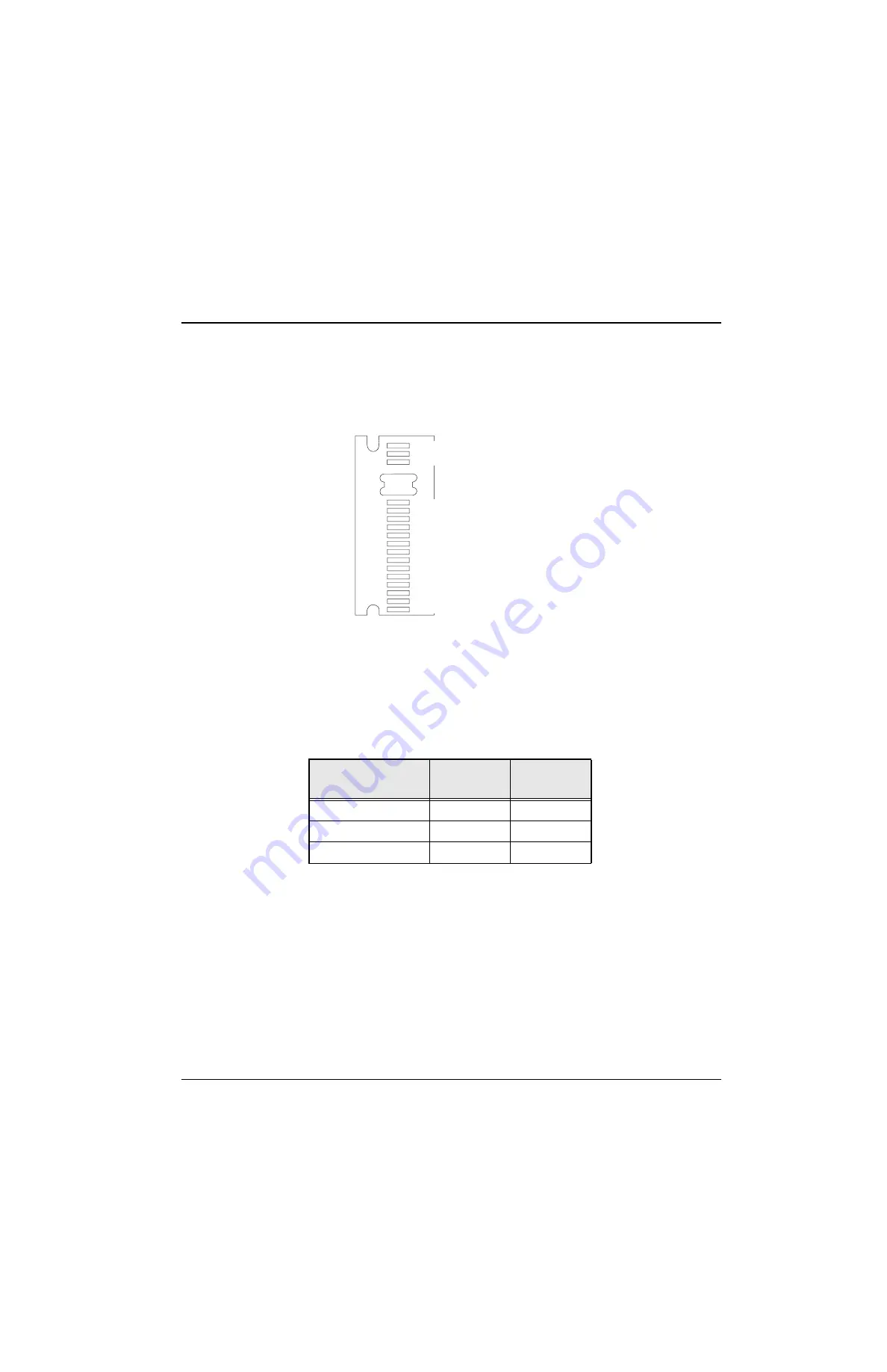
The CE connector is located on the bottom side of the radio. It is the external port or interface to the
outside and is used for programming and interfacing to external accessories. The CE connector
connects to the VOCON section at connector J2 via a flex circuit (UCM-CE-Audio Jack Flex) that is
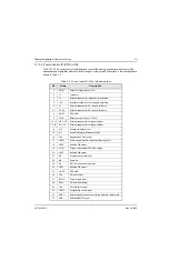
routed inside the external housing. Pin assignments on the CE connector are shown in
.
Figure 3-8. CE Connector
Most of the signals are extensions of circuits described in other areas of this manual. However, there
are two option select pins (see
) used to configure special modes: Option Select 1 and
Option Select 2. These pins are controlled by accessories connected to the universal connector.
outlines their functions as defined at the universal connector.
3.2.4.4 Dual Display Module
The XTS4000 radio has a dual display module within the front-flip assembly of the radio. The dual
display consists of a main display and a caller identification CID display. The main display is a 130 x
130 dot matrix liquid crystal display (LCD) whereas the CID display is a 112 x 32 dot matrix LCD. The
display module uses chip on film technology and is not field repairable.
3.2.4.5 Keypad
The keypad on the XTS4000 radio is a 3 x 3 Menu Keypad (with 4-way navigation button) and a 3 x
4 alphanumeric keypad. This keypad is realized through a flex circuit design which is housed within
the front-flip assembly of the radio. The keypad is connected to the VOCON section through
connector J1.
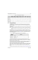
Table 3-4. Option-Select Functions
Function
Option
Select 1
Option
Select 2
External PTT
0
0
No Function (Normal)
1
1
External Speaker
0
1
1
3
4
17
CE_GND
CE_NC1
_VPP
CE_RS232
CE_RS232_RX_USB
CE_RTS
CE_CTS
CE_LH_DATA_KEYFAIL
CE_EXT_MIC
CE_NC3
CE_NC4
CE_OPT_SEL1
CE_OPT_SEL2
CE_EXTSPKR
CE_SPKRCOM
CE_NC5
CE_NC2
Summary of Contents for ASTRO XTSTM 4000
Page 1: ...COLOR CHORDS 7 ASTRO XTSTM 4000 Portable Radio Detailed Service Manual ...
Page 2: ......
Page 16: ...May 28 2008 6871620L01 C xiv Commercial Warranty Notes ...
Page 22: ...May 28 2008 6871620L01 C 1 6 Introduction Notes ...
Page 26: ...May 28 2008 6871620L01 C 2 4 Radio Power Notes ...
Page 56: ...May 28 2008 6871620L01 C 3 30 Theory of Operation Notes ...
Page 100: ...May 28 2008 6871620L01 C 6 8 Troubleshooting Waveforms Notes ...
Page 194: ...May 28 2008 6871620L01 C B 2 Motorola Service Centers Notes ...
Page 204: ...May 28 2008 6871620L01 C Glossary 10 Glossary Notes ...
Page 209: ......

