background image

6-18

Radio Alignment Procedures

: Performance Testing

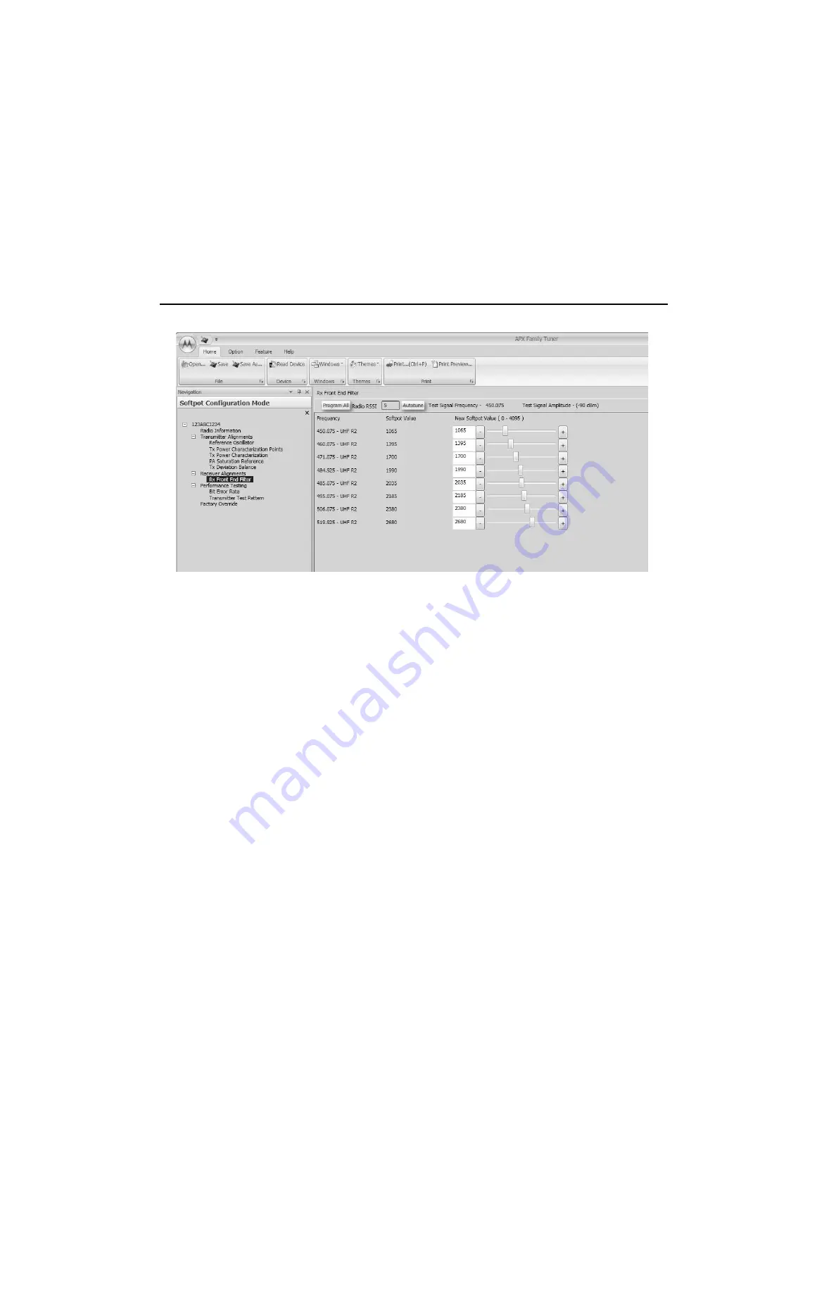
Figure 6-22.  Front End Filter Alignment Screen (UHF2)

6.7

Performance Testing

6.7.1

Bit Error Rate

This section describes the Bit Error Rate (BER) test of the radio’s receiver at a desired frequency 
(see 

Figure 6-23

Figure 6-24

Figure 6-25

 and 

Figure 6-26

).

6.7.1.1  Bit Error Rate Fields

Set up the R2670 Communication Analyzer as follows:

1. Connect the RF Input port of the radio under test to the RF IN/OUT port of the R2670 Service 

Monitor.

2. Set up the R2670 Service Monitor:

- In the Display Zone, select PROJ 25 STD mode and set the meter to RF DISPLAY.
- In the RF Zone, configure the analyzer as follows:

- In the Audio Zone, select the 1011 Hz PAT code and set the deviation to “PROJ25Dev: 

2.83 kHz ~”.

The bit error rate screen contains the following fields:

Rx Frequency

:

This field selects the Receive Frequency directly in MHz.

RF Control:

Generate

Preset:

B/W: NB

Freq:

Test frequency (Ex: 851.0625 MHz)

Output Level:

-50.0 dBm

Gen RF Out:

RF I/O

Summary of Contents for APX 4000

Page 1: ...APXTM TWO WAY RADIOS APX 1000 APX 2000 APX 4000 APX 4000Li BASIC SERVICE MANUAL ...

Page 2: ...ive rights for copyrighted computer programs including but not limited to the exclusive right to copy or reproduce in any form the copyrighted computer program Accordingly any copyrighted Motorola computer programs contained in the Motorola products described in this manual may not be copied reproduced modified reverse engineered or distributed in any manner without the express written permission ...

Page 3: ...4000 APX 4000Li Digital Portable Radios Basic Service Manual Contents Section 1 APX 2000 APX 4000 APX 4000 Li Section 2 APX 1000 VHF UHF1 UHF2 700 800 MHz Section 3 APX 1000 900 MHz Section 4 APX 2000 APX 4000 Two Knobs Section 5 Appendices ...

Page 4: ...56 D 1 Updated APX 4000Li Model 2 information Model Chart 2 Updated Model Numbering Chart 3 Updated Chapter 4 Recommended Test Equipment and Service Aids Changed CPS and Tuner software part no 4 Updated Chapter 10 Exploded Views and Parts List June 2013 68012004056 E 1 Updated Model Chart 2 Updated Chapter 10 Exploded Views and Parts List Nov 2013 68012004056 F 1 Added information for Soldier Gree...

Page 5: ...arranty iii Commercial Warranty For details on the regional Motorola Service Centers Replacement Parts Ordering and Technical Support assistance refer to the relevant regions in the Appendix section of this manual ...

Page 6: ...Notes iv Commercial Warranty ...

Page 7: ...Title Page ASTRO APX 2000 APX 4000 APX 4000 Li Digital Portable Radios Section 1 APX 2000 APX 4000 APX 4000Li ...

Page 8: ...ii Notes ...

Page 9: ... Model Chart xv ASTRO APX 2000 APX 4000 APX 4000Li UHF2 Model Chart Continued xvi ASTRO APX 2000 APX 4000 APX 4000Li 700 800 MHz Model Chart xvii ASTRO APX 2000 APX 4000 APX 4000Li 700 800 MHz Model Chart Continued xviii ASTRO APX 4000 900 MHz Model Chart xix Specifications for APX 2000 APX 4000 APX 4000Li VHF Radios xx Specifications for APX 2000 APX 4000 APX 4000Li UHF1 Radios xxi Specifications...

Page 10: ...gnment Procedures 6 1 6 1 Test Setup 6 1 6 2 Tuner Main Menu 6 2 6 3 Softpot 6 2 6 4 Radio Information 6 4 6 5 Transmitter Alignments 6 4 6 6 Front End Filter Alignment 6 22 6 7 Performance Testing 6 23 Chapter 7 Encryption 7 1 7 1 Load an Encryption Key 7 1 7 2 Multikey Feature 7 2 7 3 Select an Encryption Key 7 2 7 4 Select an Encryption Index 7 3 7 5 Erase an Encryption Key 7 4 Chapter 8 Disass...

Page 11: ...oting 9 4 9 5 Encryption Troubleshooting 9 4 Chapter 10 Exploded Views and Parts Lists 10 1 10 1 APX 2000 APX 4000 APX 4000Li Front Kit Exploded View 10 2 10 2 APX 2000 APX 4000 APX 4000Li Front Kit Exploded View Parts List 10 3 10 3 APX 2000 APX 4000 APX 4000Li Back Kit Exploded View 10 4 10 4 APX 2000 APX 4000 APX 4000Li Back Kit Exploded View Parts List 10 5 Index Index 1 ...

Page 12: ...5 9 Transmitter Tests for ASTRO Conventional Channels APX 2000 APX 4000 APX 4000Li 5 11 Table 6 1 Reference Oscillator Alignment 6 8 Table 7 1 Kit Numbers for Secure Enabled Keypad Boards 7 1 Table 8 1 APX 2000 APX 4000 APX 4000Li Partial Exploded View Parts List 8 2 Table 8 2 Required Tools and Supplies 8 3 Table 8 3 Required Tools and Supplies 8 3 Table 9 1 Power Up Error Code Displays 9 1 Table...

Page 13: ...Power Characterization Points Alignment Screen 700 800MHz 6 11 Figure 6 14 Transmit Power Characterization Points Alignment Screen 900MHz 6 11 Figure 6 15 Transmit Power Characterization Alignment Screen VHF 6 12 Figure 6 16 Transmit Power Characterization Alignment Screen UHF1 6 13 Figure 6 17 Transmit Power Characterization Alignment Screen UHF2 6 13 Figure 6 18 Transmit Power Characterization A...

Page 14: ...ypad 8 14 Figure 8 22 Serviceable Components Main Board Assembly 8 15 Figure 8 23 Serviceable Components Chassis Assembly 8 16 Figure 8 24 Serviceable Components Main Housing 8 18 Figure 8 25 Servicing the Multi Function Knob 8 19 Figure 8 26 Assemble the RF Board 8 20 Figure 8 27 Assemble the Main O Ring at Antenna Holder 8 20 Figure 8 28 Assemble the Secondary Shield Assembly 8 21 Figure 8 29 To...

Page 15: ...kHz 5 15kHz 6 20 25kHz 7 30kHz 9 Variable Programmable Typical Model Number Position Position 8 Primary Operation Conventional Simplex Conventional Duplex Trunked Twin Type Dual Mode Trunked Dual Mode Trunked Duplex Trunked Type I Trunked Type II FDMA Digital Dual Mode TDMA Digital Dual Mode Single Sideband Global Positioning Satellite Capable Amplitude Companded Sideband ACSB Programmable FDMA Fr...

Page 16: ...x Portable Radio Model Numbering System Notes ...

Page 17: ...ypad Board Model 3 Base X X PMLN6209_ Assembly Keypad Board Model 3 Expanded X X 40012085001 Mylar with Metal Domes Model 1 5 Keypad X X 40012056002 Mylar with Metal Domes Model 2 Keypad X X 40012056001 Mylar with Metal Domes Model 3 Keypad X X X X X X 0104059J61 Assembly Flex Back Mic X X X X X X 35012068001 Membrane Back Mic X X X X X X 32012282001 Boot Back Mic X X X X X X 64012022001 Backer Ba...

Page 18: ...ck APX 4000 54012198003 Label Back APX 4000Li X X X X X X 54012241001 Label Bottom 54012255001 Label Front Color Talk Group O O O O O O 54012230001 Label FM X X X X X X 36012020002 Knob Multi Function X X X X X X 15012142001 Cover Accessory Connector X X X X X X PMLN5997_ User Guide CD APX 2000 and APX 4000 Note X Item Included Option available Can be serviced in depot and ordered thru AAD O Optio...

Page 19: ... Keypad Board Model 3 Base X X PMLN6209_ Assembly Keypad Board Model 3 Expanded X X 40012085001 Mylar with Metal Domes Model 1 5 Keypad X X 40012056002 Mylar with Metal Domes Model 2 Keypad X X 40012056001 Mylar with Metal Domes Model 3 Keypad X X X X X X 0104059J61 Assembly Flex Back Mic X X X X X X 35012068001 Membrane Back Mic X X X X X X 32012282001 Boot Back Mic X X X X X X 64012022001 Backer...

Page 20: ...ack APX 4000 54012198003 Label Back APX 4000Li X X X X X X 54012241001 Label Bottom 54012255001 Label Front Color Talk Group O O O O O O 54012230001 Label FM X X X X X X 36012020002 Knob Multi Function X X X X X X 15012142001 Cover Accessory Connector X X X X X X PMLN5997_ User Guide CD APX 2000 and APX 4000 Note X Item Included Option available Can be serviced in depot and ordered thru AAD O Opti...

Page 21: ...Keypad Board Model 3 Base X X PMLN6209_ Assembly Keypad Board Model 3 Expanded X X 40012085001 Mylar with Metal Domes Model 1 5 Keypad X X 40012056002 Mylar with Metal Domes Model 2 Keypad X X 40012056001 Mylar with Metal Domes Model 3 Keypad X X X X X X 0104059J61 Assembly Flex Back Mic X X X X X X 35012068001 Membrane Back Mic X X X X X X 32012282001 Boot Back Mic X X X X X X 64012022001 Backer ...

Page 22: ...ack APX 4000 54012198003 Label Back APX 4000Li X X X X X X 54012241001 Label Bottom 54012255001 Label Front Color Talk Group O O O O O O 54012230001 Label FM X X X X X X 36012020002 Knob Multi Function X X X X X X 15012142001 Cover Accessory Connector X X X X X X PMLN5997_ User Guide CD APX 2000 and APX 4000 Note X Item Included Option available Can be serviced in depot and ordered thru AAD O Opti...

Page 23: ... X PMLN6211_ Assembly Keypad Board Model 2 Expanded X X PMLN6212_ Assembly Keypad Board Model 3 Base X X PMLN6209_ Assembly Keypad Board Model 3 Expanded X X 40012085001 Mylar with Metal Domes Model 1 5 Keypad X X 40012056002 Mylar with Metal Domes Model 2 Keypad X X 40012056001 Mylar with Metal Domes Model 3 Keypad X X X X X X 0104059J61 Assembly Flex Back Mic X X X X X X 35012068001 Membrane Bac...

Page 24: ...00 54012198002 Label Back APX 4000 54012198003 Label Back APX 4000Li X X X X X X 54012241001 Label Bottom 54012255001 Label Front Color Talk Group O O O O O O 54012230001 Label FM X X X X X X 36012020002 Knob Multi Function X X X X X X 15012142001 Cover Accessory Connector X X X X X X PMLN5997_ User Guide CD APX 2000 and APX 4000 Note X Item Included Option available Can be serviced in depot and o...

Page 25: ... 7515719H02 Pad Thermal RF PA X X 43012045001 Collar Plastic X X 6071520M01 Coin Cell X X 0104043J76 Assembly Flex Back kit Model 2 and Model 3 X X 0104046J48 Assembly Shield Secondary X X 0386104Z04 Screw Chassis X X 3286058L01 Seal Vacuum Port X X 5478220A01 Label Ventilation 54012196001 Label Front_NamePlate Bluetooth Blue Dot Expanded 54012198002 Label Back APX 4000 X X 54012241001 Label Botto...

Page 26: ...h D Depth 1 Width Top Width PTT 2 Depth Bottom Depth PTT Weight w o Antenna Less Battery 9 17 oz 260g With Li Ion Standard 14 47 oz 410g With Li Ion High Cap 14 81 oz 420g Frequency Range 136 174 MHz Bandwidth 38 MHz Analog Sensitivity typical 12 dB SINAD 0 216µV Digital Sensitivity typical 1 BER 0 285 µV 5 BER 0 188 µV Intermodulation typical 79 dB Selectivity typical 25 kHz Channel 79 3 dB 12 5 ...

Page 27: ...Width D Depth 1 Width Top Width PTT 2 Depth Bottom Depth PTT Weight w o Antenna Less Battery 9 17 oz 260g With Li Ion Standard 14 47 oz 410g With Li Ion High Cap 14 81 oz 420g Frequency Range 380 470 MHz Bandwidth 90 MHz Analog Sensitivity typical 12 dB SINAD 0 234µV Digital Sensitivity typical 1 BER 0 307 µV 5 BER 0 207 µV Intermodulation typical 77 dB Selectivity typical 25 kHz Channel 77 dB 12 ...

Page 28: ...Width D Depth 1 Width Top Width PTT 2 Depth Bottom Depth PTT Weight w o Antenna Less Battery 9 17 oz 260g With Li Ion Standard 14 47 oz 410g With Li Ion High Cap 14 81 oz 420g Frequency Range 450 520 MHz Bandwidth 70 MHz Analog Sensitivity typical 12 dB SINAD 0 234µV Digital Sensitivity typical 1 BER 0 307 µV 5 BER 0 207 µV Intermodulation typical 77 dB Selectivity typical 25 kHz Channel 77 dB 12 ...

Page 29: ...Weight w o Antenna Less Battery 9 17 oz 260g With Li Ion Standard 14 47 oz 410g With Li Ion High Cap 14 81 oz 420g Frequency Range 700 MHz 764 776 MHz 800 MHz 851 870 MHz Bandwidth 700 MHz 12 MHz 800 MHz 19 MHz Analog Sensitivity typical 12 dB SINAD 0 266µV Digital Sensitivity typical 1 BER 0 400 µV 5 BER 0 266 µV Intermodulation typical 75 dB Selectivity typical 25 kHz Channel 76 dB 12 5 kHz Chan...

Page 30: ...m D2 1 69 42 9mm 1 93 48 9mm Note H Height W Width D Depth 1 Width Top Width PTT 2 Depth Bottom Depth PTT Weight w o Antenna Less Battery 9 17 oz 260g With Li Ion Standard 14 47 oz 410g With Li Ion High Cap 14 81 oz 420g Frequency Range 935 941 MHz Bandwidth 6 MHz Analog Sensitivity typical 12 dB SINAD 0 236µV Digital Sensitivity typical 1 BER 0 33 µV 5 BER 0 222 µV Intermodulation typical 75 dB S...

Page 31: ...recommended test equipment service aids radio alignment procedures general maintenance recommendations procedures for assembly and disassembly and exploded views and parts lists 1 2 Notations Used in This Manual Throughout the text in this publication you will notice the use of note caution warning and danger notations These notations are used to emphasize that safety hazards exist and due care mu...

Page 32: ...dio s features and capabilities meant significant modifications or buying a new radio But now similar to how a computer can be loaded with different software the radio s features and capabilities can be upgraded with FLASHport software Table 1 1 ASTRO APX 2000 APX 4000 APX 4000Li Basic Features Feature Standard Control Model 1 5 Limited Keypad Model 2 Full Keypad Model 3 Display Full bitmap color ...

Page 33: ... of a mild dishwashing detergent in water The detergent water solution should be applied sparingly with a stiff non metallic short bristled brush to work all loose dirt away from the radio A soft absorbent lintless cloth or tissue should be used to remove the solution and dry the radio Make sure that no water remains entrapped near the connectors cracks or crevices 2 2 Safe Handling of CMOS and LD...

Page 34: ...00 APX 4000 APX 4000Li radio has a vent port that allows for pressure equalization in the radio Never poke this vent with any objects such as needles tweezers or screwdrivers This could create a leak path into the radio and the radio s submergibility will be lost The pressure equalization vent is located adjacent to the battery contact opening of the main chassis Never touch the equalization vent ...

Page 35: ... 450 520 MHz 700 800 MHz 764 870 MHz All ASTRO APX 2000 APX 4000 APX4000 Li radios besides the radios with 900 MHz are capable of analog operation 12 5 kHz or 25 kHz bandwidths ASTRO mode digital operation 12 5 kHz only X2 TDMA mode 25 kHz only and Phase 2 TDMA mode 12 5 kHz only For radios with 900 MHz they support analog operation 12 5 kHz only ASTRO mode digital operation 12 5 kHz only and Phas...

Page 36: ...th 2 1 IC and front end circuitry Keypad Board Contains a Type III secure IC Bluetooth controller AVR IC and a 3 axes digital accelerometer Control Top Contains a Multi Function knob a push button switch used for Emergency call and a light bar The control top also includes TX RX LED that is solid amber upon receive red on PTT and blinks amber on secure TX RX Main Display 160 pixels x 90 pixels tra...

Page 37: ...ntains a switchable attenuator that is enabled at predetermined RF power thresholds present at the antenna port See Figure 3 2 Figure 3 3 Figure 3 4and Figure 3 5 Figure 3 2 Receiver Block Diagram VHF Figure 3 3 Receiver Block Diagram UHF1 UHF2 Antenna Switch 15 dB Step Attenuator VHF VHF IF Filter DIG_CTRL_ATTH Rx LO To GPS Diplexer SSI 18Mhz CLK Abacus III ABACUS III Dec Filter ΣΔ ADC 2nd LO LO ...

Page 38: ...tween the radio RF and GPS signal paths The GPS signal is filtered though a GPS SAW filter LNA Saw filter chain before going into the TI GPS IC for processing Figure 3 6 GPS Diagram 15 dB Step Attenuator Antenna Switch SW DIG_CTRL_ATTH 700 800 700 800 Rx LO IF Filter To GPS Diplexer SW SW SW SSI 18Mhz CLK Abacus III ABACUS III Dec Filter ΣΔ ADC 2nd LO LO CLK Antenna Switch 15 dB Step Attenuator 90...

Page 39: ...cond LNA whose output is applied to a discrete image filter Both preselector filters are Surface Acoustic Wave designs used to band limit the received energy and suppress known spurious responses such as Image and the IF spur The output of the discrete image filter is applied to the RF port of the Mixer IC The Mixer IC is also excited by a Local Oscillator LO signal at the LO port to down convert ...

Page 40: ... 3 8 Transmitter UHF1 UHF2 Block Diagram Trident IC Synthesizer Loop Filter TX VCO RX TX VCO RF Switch Matrix TX Buffer Amp TX Driver Amplifier Transmitter Final FET VHF Harmonic LP Filter Ref Oscillator Antenna Connector Directional Coupler Antenna Switch TO RX GPS Reverse Power Detection Log Amp Power Detector Digital RF Attenuator Trident IC Synthesizer Loop Filter TX VCO RX TX VCO RF Switch Ma...

Page 41: ...monics of the carrier signal and then passes through a directional coupler The Log Amp power detector Monitors the output of the directional coupler and adjusts the control voltages to the driver amplifier and final power amplifier Finally the RF signal is routed to the main antenna Trident IC Synthesizer Loop Filter TX VCO RX TX VCO RF Switch Matrix TX Buffer Amp TX Driver Amplifier Transmitter F...

Page 42: ...r which amplifies the signal The signal is routed to the 7800 Driver amplifier and then to the discrete final power amplifier The signal now goes through the antenna switch which routes the power to the harmonic filter which will filter out the harmonics of the carrier signal and then passes through a directional coupler The Log Amp power detector Monitors the output of the directional coupler and...

Page 43: ...ystem The Power and Clocks section includes a power management IC MAKO and various external switching regulators and three clock sources 12 MHz and 24 576 MHz from which all other controller digital clocks are derived The Audio section has a CODEC and a class D audio power amplifier that provides the radio with a microphone and speaker design The User Interface section provides communication and c...

Page 44: ...internal 4 Ohm speaker is located on the same side as the main display and keypad of the radio The internal speaker is driven by a Class D audio amplifier located on the main board that is capable of delivering a rated power of 0 5 W The external accessory speaker is driven by a Class AB audio amplifier on the MAKO IC that is capable of delivering 0 5 W of power into a 16 Ohm as a minimum load Bot...

Page 45: ...cated on the keypad board over an HCI UART link The AVR32 processor communicates to the OMAP processor on the main board through a dedicated USB port The Bluetooth feature is accompanied by a Low Frequency LF detection circuit that is also located on the keypad board The LF circuit provides the ability of a secure pairing connection with a Bluetooth accessory Once a radio has the Bluetooth feature...

Page 46: ...3 12 Basic Theory of Operation Controller Section Notes ...

Page 47: ...cteristics Example Application Service Monitor Can be used as a substitute for items marked with an asterisk General Dynamics R2670 Frequency deviation meter and signal generator for wide range troubleshooting and alignment Digital RMS Multimeter 100 µV to 300 V 5 Hz to 1 MHz 10 Mega Ohm Impedance Fluke 179 or equivalent www fluke com AC DC voltage and current measurements Audio voltage measuremen...

Page 48: ...nformation Table 4 2 Service Aids Motorola Part Number Description Application 66012028001 Chassis Opener To disassemble chassis from housing 66012031001 Battery Adapter Used in place of battery to connect radio to an external power supply 66012030001 Vacuum Test Fixture To connect the vacuum pressure hose to the radio NLN9839_ Vacuum Pump Kit Vacuum pump with gauge and vacuum hose Requires Vacuum...

Page 49: ...on schedule Checks should be performed if radio performance degradation is suspected 5 1 Test Equipment Setup Supply voltage can be connected from the battery eliminator The equipment required for the performance checks is connected as shown in Figure 5 1 Figure 5 1 Performance Checks Test Setup BNC NOT USED AUDIO GENERATOR SINAD METER AC VOLTMETER TX RX 30 dB PAD 30 dB PAD RF GENERATOR SYSTEM ANA...

Page 50: ...onitor Mode Standard Spkr Load Speaker Voltage 7 5 Vdc Receiver Checks RF Control GEN Output Level 47 dBm Modulation 1 kHz tone 3 kHz deviation Frequency Set to selected radio RX frequency Meter AC Volts Transmitter Checks RF Control Monitor Frequency Set to selected radio TX frequency Meter RF Display Modulation Type FM Attenuation 20 dB PTT OFF center DC On Standby Standby Meter Out RX Volt Rang...

Page 51: ...ame Encryption Type 1 Type of encryption being used When the radio is secure equipped KG2 algorithms name Encryption Type 2 Type of encryption being used When the radio is secure equipped and 2 or more algorithms are loaded KG3 algorithms name Encryption Type 3 Type of encryption being used When the radio is secure equipped and 3 or more algorithms are loaded KG4 algorithms name Encryption Type 4 ...

Page 52: ... 5 2 3 Control Top and Keypad Test Mode on page 1 5 7 NOTE Each press of the Top Side Button Purple button scrolls through RF TEST CH TEST and RGB TEST Press the Top Button Orange button to stop the displays and put the radio into the RF test mode The test mode menu 1 CSQ is displayed indicating test frequency 1 Carrier SQuelch mode Go to Section 5 2 2 RF Test Mode below NOTE Once your radio is in...

Page 53: ...to Table 5 3 and Table 5 4 Pressing Side Button 1 scrolls through and accesses the test environments shown in Table 5 5 Pressing Top Side Button scrolls through the Tx Deviation Frequency NOTE Transmit into a load when keying a radio under test Table 5 3 Test Frequencies MHz VHF UHF1 UHF2 Test Channel VHF UHF1 UHF2 RX TX RX TX RX TX F1 136 075 136 025 380 075 380 025 450 075 450 025 F2 142 075 142...

Page 54: ...5 809 0125 938 0625 938 0125 F6 869 9375 823 9875 940 9875 940 9375 F7 851 0625 851 0125 F8 860 0625 860 0125 F9 869 9375 869 8875 F10 Table 5 5 Test Environments Display Description Function CSQ Carrier Squelch RX unsquelch if carrier detected TX mic audio TPL Tone Private Line RX unsquelch if carrier and tone 192 8 Hz detected TX mic audio tone 192 8 Hz AST ASTRO RX none TX Digital Voice USQ Car...

Page 55: ...play values may vary slightly at the upper and lower limits Press gives 91 1 release gives 91 0 5 Press the Top Side Button 96 1 appears release 96 0 appears 6 Press Side Button 1 97 1 appears release 97 0 appears 7 Press Side Button 2 98 1 appears release 98 0 appears 8 Press the PTT Button 1 1 appears release 1 0 appears 5 2 4 RGB Test Mode To perform the RGB Color Test 1 Press and release Top B...

Page 56: ...00 MHz 1 5ppm 1146 1305 Hz 900 MHz 1 5ppm Rated Audio RF Control Gen Output Level 47 dBm Freq Selected radio RX freq Mod 1 kHz tone 3 kHz dev Meter AC Volts As above PTT to OFF center Set volume control to 3 74 Vrms Distortion As above except Meter Ext Dist As above As above Distortion 3 0 Sensitivity SINAD As above except Meter SINAD As above As above RF input to be 0 35 µV Noise Squelch Threshol...

Page 57: ...As above As above Output level 0 35 µV 116 dBm Use test setup shown in Figure 6 1 Audio Output Distortion Mode Proj 25 Std RF Control Gen Output Level 47 dBm Proj 25 Dev 2 83 kHz Code 1011 Hz PAT Meter Ext Distortion Radio Tuner Software not used Radio Out of TEST MODE Select a conventional ASTRO channel PTT to OFF center Meter selector to Audio PA Spkr Load to Speaker Distortion 3 0 Residual Audi...

Page 58: ... As above Set fixed 1 kHz audio level to 400 mV As above As above Deviation 12 5 kHz 2 1 kHz but 2 5 kHz 25 kHz 4 1 kHz but 5 0 kHz Voice Modulation internal RF Control Monitor Meter RF Display Display Bar Graphs Freq Selected radio TX freq As above Remove modulation input PTT to OFF center Press PTT button on radio Say four loudly into the radio mic Measure deviation 12 5 kHz 2 1 kHz but 2 5 kHz ...

Page 59: ...ASTRO channel PTT to continuous during measurement VHF 1 5 Watt UHF1 1 5 Watt UHF2 1 5 Watt 700 1 2 7 Watt 800 1 3 Watt 900 1 2 5 Watt Frequency Error As above As above As above Error 1 0 kHz Frequency Deviation As above Radio Tuner Software Transmitter Test Pattern screen is required High use Symbol Rate PAT Low use Low Symbol Rate P PTT to OFF center DHIGH 2 543 kHz but 3 110 kHz DLOW 0 841 kHz ...

Page 60: ...5 12 Performance Checks Transmitter Performance Checks Notes ...

Page 61: ...alignment test setup is shown in Figure 6 1 Figure 6 1 Radio Alignment Test Setup These radio alignment procedures should only be attempted by qualified service personnel Failure to perform alignment procedures properly may result in seriously degraded radio or system performance BNC COMPUTER AUDIO GENERATOR SINAD METER AC VOLTMETER TX RX 30 dB PAD 30 dB PAD RF GENERATOR SYSTEM ANALYZER OR COUNTER...

Page 62: ...lignment screens introduce the concept of the softpot an analog SOFTware controlled POTentiometer used for adjusting all transceiver alignment controls Each alignment screen provides the ability to increase or decrease the softpot value by using a slider or by entering the new value from the keyboard directly into the box The slider bar indicates the current softpot value see Figure 6 3 DO NOT swi...

Page 63: ...rocomputer to increase the voltage across a varactor in the reference oscillator which increases the frequency In ALL cases the softpot value is just a relative number corresponding to a digital to analog D A generated voltage in the radio Perform the following procedures in the sequence indicated NOTE Some of the following screens may vary depending upon the radio under test and the version of tu...

Page 64: ...illator is critical for proper radio operation Improper adjustment will result not only in poor operation but also in a misaligned radio that will interfere with other users operating on adjacent channels For this reason the reference oscillator should be checked every time the radio is serviced or once a year whichever comes first The frequency counter used for this procedure must have a stabilit...

Page 65: ...y Mode STD Input Level uV or W Display Bar Graphs Squelch Mid range or adjust as necessary Initial setup using the 8901_ Series Modulation Analyzer Press the green Automatic Operation button on the analyzer Press the FREQ key Type 7 1 followed by SPCL button to set the 8901B_ modulation analyzer for maximum accuracy To align the reference oscillator Select the Reference Oscillator alignment screen...

Page 66: ...6 6 Radio Alignment Procedures Transmitter Alignments Figure 6 6 Reference Oscillator Alignment Screen UHF1 Figure 6 7 Reference Oscillator Alignment Screen UHF2 ...

Page 67: ...Radio Alignment Procedures Transmitter Alignments 6 7 Figure 6 8 Reference Oscillator Alignment Screen 700 800 MHz Figure 6 9 Reference Oscillator Alignment Screen 900 MHz ...

Page 68: ... 2 Adjust the reference oscillator s softpot value with the slider until the measured value is as close as possible to the frequency shown on the screen See Table 6 1 NOTE Increases the slider decreases the frequency and vice versa 3 Left click the Program All button on the screen to dekey the radio and save the tuned values 4 Left click the Close button on the screen to return to the Transmitter ...

Page 69: ...ly voltage and current limit 3 Adjust softpot value by manipulating the slider bar incrementing the New Softpot Value text box or directly entering the desired value into the New Softpot Value text box until the rated power is indicated on the service Monitor For rated power refer to the help text in the Tuner 4 Repeat step 2 to 3 for all frequencies 5 Left click the Program All button on the scre...

Page 70: ...6 10 Radio Alignment Procedures Transmitter Alignments Figure 6 11 Transmit Power Characterization Points Alignment Screen UHF1 Figure 6 12 Transmit Power Characterization Points Alignment Screen UHF2 ...

Page 71: ...o Alignment Procedures Transmitter Alignments 6 11 Figure 6 13 Transmit Power Characterization Points Alignment Screen 700 800 MHz Figure 6 14 Transmit Power Characterization Points Alignment Screen 900 MHz ...

Page 72: ...sure Power 1 for the desired frequency field The selected box is highlighted 3 Click the PTT Toggle button on the screen to make the radio transmit The screen indicates whether the radio is transmitting 4 Measure the transmit power of the radio with a service Monitor 5 Input the transmit power in watts using two decimal places into the highlighted Measure Power 1 box 6 Left click the box under Mea...

Page 73: ...Radio Alignment Procedures Transmitter Alignments 6 13 Figure 6 16 Transmit Power Characterization Alignment Screen UHF1 Figure 6 17 Transmit Power Characterization Alignment Screen UHF2 ...

Page 74: ...6 14 Radio Alignment Procedures Transmitter Alignments Figure 6 18 Transmit Power Characterization Alignment Screen 700 800 MHz Figure 6 19 Transmit Power Characterization Alignment Screen 900 MHz ...

Page 75: ...aturation Reference alignment screen 3 Adjust the PA Saturation Reference softpot value with the slider until the radio transmits as close as possible to the rated power For rated power refer to the help text in the Tuner 4 Left click the slider of the frequency selected should be the same frequency as step 2 5 Left click the PTT Toggle button on the screen to make the radio transmit The screen in...

Page 76: ...6 16 Radio Alignment Procedures Transmitter Alignments Figure 6 21 PA Saturation Referencing Alignment Screen UHF1 Figure 6 22 PA Saturation Referencing Alignment Screen UHF2 ...

Page 77: ...Radio Alignment Procedures Transmitter Alignments 6 17 Figure 6 23 PA Saturation Referencing Alignment Screen 700 800 MHz Figure 6 24 PA Saturation Referencing Alignment Screen 900 MHz ...

Page 78: ...CTIONS MENU Move the cursor to High Pass and select 5 Hz on the soft key menu Select 20 kHz for the Low Pass setting In the RF Control section of the R 2670 move the cursor to the B W setting and select WIDE 100 kHz on the soft key menu Place the R 2670 cursor in the Display zone Select AC VOLTS on the soft key menu Move the cursor to the Range setting and select AUTO 2 Initial setup using the 890...

Page 79: ...9 11 Left click the PTT Toggle to de key the radio 12 Repeat the steps 4 to 10 for all frequencies 13 Left click the Program All button on the screen to dekey the radio and save the tuned values Figure 6 25 Transmit Deviation Balance Alignment Screen VHF ...

Page 80: ...6 20 Radio Alignment Procedures Transmitter Alignments Figure 6 26 Transmit Deviation Balance Alignment Screen UHF1 Figure 6 27 Transmit Deviation Balance Alignment Screen UHF2 ...

Page 81: ...Radio Alignment Procedures Transmitter Alignments 6 21 Figure 6 28 Transmit Deviation Balance Alignment Screen 700 800 MHz Figure 6 29 Transmit Deviation Balance Alignment Screen 900 MHz ...

Page 82: ...6 6 1 Procedure for UHF 1 and UHF2 Auto Tune Tuning of the radio is done through Rx Front End Filter tuning screen 1 Select the Rx Front End Filter alignment screen See Figure 6 30 2 Click on the slider or the New Softpot Value text box to select which frequency to tune 3 Apply RF test signal input with no modulation at 90 dBm on the Test Signal Frequency displayed at the top of the screen 4 Left ...

Page 83: ...ows 1 Connect the RF Input port of the radio under test to the RF IN OUT port of the R2670 Service Monitor 2 Set up the R2670 Service Monitor In the Display Zone select PROJ 25 STD mode and set the meter to RF DISPLAY In the RF Zone configure the analyzer as follows In the Audio Zone select the 1011 Hz PAT code and set the deviation to PROJ25Dev 2 83 kHz The bit error rate screen contains the foll...

Page 84: ...This field allows the user to select the audio output during a test Selecting Internal will cause the radio s built in speaker to unmute to any signals at the desired frequency which are present during the test Selecting External will route the same signal to the radio s accessory connector audio output Selecting Mute will disable the audio output NOTE There will be no audio option available for A...

Page 85: ...Radio Alignment Procedures Performance Testing 6 25 Figure 6 32 Bit Error Rate Screen VHF Figure 6 33 Bit Error Rate Screen UHF1 ...

Page 86: ...6 26 Radio Alignment Procedures Performance Testing Figure 6 34 Bit Error Rate Screen UHF2 Figure 6 35 Bit Error Rate Screen 700 800 MHz ...

Page 87: ... Figure 6 39 Figure 6 40 and Figure 6 41 6 7 2 1 Transmitter Test Fields This screen contains the following fields Tx Frequency This field selects the Transmit Frequency directly in MHz Channel Spacing This field allows the user to select the desired transmit deviation in kHz Test Pattern Type This field represents the type of test pattern which will be transmitted by the radio when PTT TOGGLE but...

Page 88: ...6 28 Radio Alignment Procedures Performance Testing Figure 6 37 Transmitter Test Pattern Screen VHF Figure 6 38 Transmitter Test Pattern Screen UHF1 ...

Page 89: ...Radio Alignment Procedures Performance Testing 6 29 Figure 6 39 Transmitter Test Pattern Screen UHF2 Figure 6 40 Transmitter Test Pattern Screen 700 800 MHz ...

Page 90: ...6 30 Radio Alignment Procedures Performance Testing Figure 6 41 Transmitter Test Pattern Screen 900 MHz ...

Page 91: ... key 1 Refer to the key variable loader KVL manual for equipment connections and setup 2 Attach the KVL to the radio KEYLOADING is shown on the main display of a configured radio All other radio functions except for power down backlight and volume are locked out 3 Refer to the KVL manual for how to load the encryption keys into the radio 4 When the key is loaded successfully you will hear On singl...

Page 92: ...or example dynamic regrouping failsoft or emergency talkgroup The radio can have operator selectable key erasure 7 3 Select an Encryption Key You can select an encryption key using either the menu or the keypad 7 3 1 Use the Menu To select an encryption key using the menu 1 Press until the display shows Key 2 Press or directly below Key The display shows the last user selected and stored encryptio...

Page 93: ...g the available keys stored in the radio For example the radio could have a group of three keys structured to one index and another group of three different keys structured to another index Changing indices makes the radio automatically switch from one set of keys to the other Every channel to which one of the original keys was tied will now have the equivalent new key instead 7 4 1 Use the Menu T...

Page 94: ...ultikey Only To zeroize an encryption key 1 Press until the display shows Eras 2 Press or directly below Eras The display shows the last user selected and stored encryption key 3 Press or v to scroll through the list of encryption keys 4 Select single encryption key or all encrytion keys deletion from the OPTN menu 5 Press o the PTT button or or directly below Exit or turn the Multi function knob ...

Page 95: ... associated parts lists This chapter also has procedures for removing and installing the APX 2000 APX 4000 APX 4000Li radio s standard accessories 8 1 APX 2000 APX 4000 APX 4000Li Exploded View Main Subassemblies This section contains the APX 2000 APX 4000 APX 4000Li radio partially exploded views NOTES Refer to Figure 8 1 the Partial Exploded View and Table 8 1 the Partial Exploded View Parts Lis...

Page 96: ...ploded View Table 8 1 APX 2000 APX 4000 APX 4000Li Partial Exploded View Parts List Item Letter Description Exploded View and Parts List A Front Kit Assembly Refer Figure 10 1 B Back Kit Assembly Refer Figure 10 2 C Battery Assembly Refer Figure 10 2 D Accessory Connector Cover Assembly Refer Figure 10 1 E Antenna Assembly Refer Figure 10 1 A E B C D ...

Page 97: ...r mushroom rib assembly and disassembly Round stick Brusia BE MO 14383 For microphone membrane assembly Allen wrench To loosen accessory connector cover thumb screw if thumb screw is too tight Anti static ground kit To place radio and components during disassembly and reassembly Vacuum Pump kit NLN9839 Motorola For vacuum test Requires 66012030001 Vacuum Test Fixture Vacuum Test Fixture 6601203000...

Page 98: ...y other accessory connected to the radio 8 4 1 Remove Battery 48 NOTE The Motorola approved battery shipped with the APX 2000 APX 4000 APX 4000Li radio is uncharged Prior to using a new battery charge it per the recommended procedure for the battery 1 With the radio turned off lift up the latch located at the bottom of the battery Figure 8 2 Lifting up the latch To avoid a possible explosion DO NO...

Page 99: ...8 5 2 While lifting the latch remove the battery by sliding it out as shown Figure 8 3 Removing the Battery 8 4 2 Remove Antenna 23 1 With the radio turned off turn the antenna counter clockwise to remove it from the radio Figure 8 4 Removing the Antenna ...

Page 100: ... Remove Multi Function Knob 22 1 Hold the radio with the top facing upward and the front of the radio facing you 2 With the Chassis Opener grasp the Multi Function Knob and pull it upward until it is free from its shaft Figure 8 5 Removing the Multi Function Knob ...

Page 101: ...ve the screw It should remain captive in the cover Figure 8 6 Removing the Thumb Screw 2 Slightly swing the Accessory Connector Cover away from radio before sliding it upward to disengage the hook 3 Pull the Accessory Connector Cover away from the radio When the accessory connector is not in use keep it covered with the Accessory Connector Cover Caution Thumb Screw with Hex Head Socket ...

Page 102: ...Chassis Opener as shown in Figure 8 7 Figure 8 7 Disengage the Chassis NOTE The Vacuum Port seal 43 and the Ventilation Label 44 must be removed each time the Chassis is removed for leak test 2 After the Chassis 41 is disengaged slide the chassis assembly down and lift it away from the Front Kit A and lay both sub assemblies on the anti static mat part of anti static ground kit as shown in Figure ...

Page 103: ...ield Assembly 32 1 Remove the chassis screws 30 as shown in Figure 8 9 Figure 8 9 Remove the chassis screws 2 With the chassis screws removed lift the Secondary Shield Assembly 32 out from the Chassis 41 as shown in Figure 8 10 Figure 8 10 Remove the Secondary Shield Assembly Chassis Screws 7 ...

Page 104: ...plug the connectors from the Back Kit Flex 31 to remove the Main Board as shown in Figure 8 12 and Figure 8 13 respectively Figure 8 12 Lift up the Main Board from the Chassis When separating the small interconnects care is needed to avoid damage to the interconnect and surrounding on board components Place the Main Board on the anti static mat or in a clean and ESD safe area to avoid electrical d...

Page 105: ... Shroud 47 1 Place the black stick into the opening below the Shroud 47 to aid the disengagement of the Shroud With the black stick still in place slide the Shroud downwards at both sides to remove the Shroud from the Chassis 41 Figure 8 14 Disengage the Shroud Figure 8 15 Remove the Shroud Back Kit Flex Connectors Black Stick ...

Page 106: ... 34 connectors unplugged from the Main Board 33 as shown in Figure 8 13 remove the Keypad Retainer Screws 29 as shown in Figure 8 16 Figure 8 16 Remove the Keypad Retainer Screws 2 Lift out the Keypad Retainer 28 from the Front Housing 16 as shown in Figure 8 17 Figure 8 17 Remove the Keypad Retainer Keypad Retainer Screws ...

Page 107: ...t Flex Connectors 2 With the connectors unplugged gently lift the Keypad Board 27 out of the Front Housing 16 with the aid of the black stick as shown in Figure 8 18 Figure 8 19 Remove the Keypad Board When separating the flex and small interconnects care is needed to avoid damage to the interconnect and surrounding on board components When lifting the Keypad Board with the black stick care is nee...

Page 108: ...h fingers or with the aid of the back of the black stick to disengage the Keypad from the rib as shown in Figure 8 20 Figure 8 20 Disengage the Keypad 2 With the Keypad 25 disengaged from the rib gently lift it out from the Front Housing 16 Figure 8 21 Remove the Keypad When disengaging and removing the Keypad care is needed to avoid tearing and damange to the Keypad Caution Black Stick s Back ...

Page 109: ... the coin cell with the Black Stick NOTE Make sure the positive side is facing upwards 3 Press the new coin cell into the battery carrier until it is secured and fully snapped into place 8 5 1 2 Servicing Thermal Pad 1 Complete steps from Section 8 4 5 1 through Section 8 4 5 3 2 Carefully peel off the pad 3 Ensure there is no debris or residue left on the amplifier s surface 4 Replace with new Th...

Page 110: ...tick to help remove any difficult sections of the label 4 Clean the area once the label is removed to ensure it is free from adhesive and debris 5 Peel the new label off its backer and place in the respective location 6 Apply slight pressure to set the adhesive Ventilation label should always be replaced when back kit assembly is removed Microphone Boot Battery Connector Seal Ventilation Label Vac...

Page 111: ...e new Main O Ring into the groove provided in the Chassis 4 Ensure that the seal is set properly and not stretched 8 5 2 5 Servicing Microphone Boot NOTE When servicing Microphone Boot the Microphone Membrane part will also need to be replaced 1 Gently remove the Back Microphone Backer 50 with the help of a Black Stick 2 Carefully remove the microphone assembly out of the chassis opening 3 With th...

Page 112: ... the surface of the microphone boss area on the Chassis Ensure that the membrane is flat with no ripples or folds Press down firmly applying slight pressure to activate the adhesive using the Round Stick 7 Ensure that the Microphone Boot is seated correctly within the chassis opening 8 With the Microphone Boot seated in the chassis carefully place the Back Microphone Backer 50 to cover the microph...

Page 113: ...1 Scrap off the FM Label with the Black Stick 2 Clean the area once the FM Label is completely removed to ensure it is free of adhesive and debris 3 Remove the label off its backer and place it in the recess 4 Press the label 8 5 4 Servicing Multi Function Knob 1 Hold the radio with the top facing upward and the front of the radio facing you 2 With the Chassis Opener grasp the Multi Function Knob ...

Page 114: ... into the Chassis 41 as shown in Figure 8 26 Figure 8 26 Assemble the RF Board NOTE Plug in the connectors at the side of the Back Kit Flex which reads To Main Board Ensure that the Battery Contact Seal 42 does not pinch and the tabs of the Main O Ring are held in place when assembling the Main Board into the Chassis 2 With the Main Board 33 seated in the Chassis 41 gently assemble the Main O Ring...

Page 115: ...assembled place the Secondary Shield Assembly 32 onto the Main Board Figure 8 28 Assemble the Secondary Shield Assembly 2 Torque all seven Chassis Screws 30 with a Torx IP6 Bit and a Torque Driver to 3 0 in lbf in the sequence as shown in Figure 8 29 Figure 8 29 Torque in the Chassis Screws Secondary Shield s Dimples 3 6 2 7 4 1 5 ...

Page 116: ...eypad 25 into the Front Housing 16 and gently flush the mushroom rib at the edges of the Keypad into the Front Housing with the aid of the back of the Black Stick Figure 8 30 Assemble the Keypad When flushing the Keypad care is needed to avoid damage to the Keypad Ensure that the Keypad is fully flushed to prevent leakage Caution Black Stick s Back ...

Page 117: ...lex Connector 3 Complete steps in Section 8 6 1 through Section 8 6 3 4 Gently plug in the connectors of the Back Kit Flex 31 to the Keypad Board as shown in Figure 8 32 Figure 8 32 Plug in the Back Kit Flex Connectors NOTE Plug in the connectors at the side of the Back Kit Flex which reads To Keypad Board When plugging in the connectors care is needed to avoid damage to the interconnect and surro...

Page 118: ...28 over the Keypad Board 27 in the Front Housing 16 as shown in Figure 8 33 Figure 8 33 Place Keypad Retainer over the Keypad Board 2 Torque all four keypad retainer screws 29 with a Torx IP6 Bit and a Torque Driver to 1 2 in lbf in the sequence as shown in Figure 8 34 Figure 8 34 Torque in the Keypad Retainer Screws 1 2 3 4 ...

Page 119: ...mble the Main Subassemblies A and B 1 Complete the steps in Section 8 6 1 through Section 8 6 5 2 Slide the Chassis assembly into the Front Housing as shown in Figure 8 36 Figure 8 36 Slide chassis assembly into Front Housing 3 With the Chassis assembly fully slided in press down the bottom part of the Chassis to lock the two subassemblies A and B together as shown in Figure 8 37 Figure 8 37 Assem...

Page 120: ...ng the cover down onto the radio Ensure the cover is seated properly and the screw is aligned into the threaded hole Figure 8 38 Engaging Hook and Seating Cover 2 Hand tighten the thumb screw clockwise until secured NOTE Do not overtighten the screw The screw should be snugged and does not allow the cover to move Figure 8 39 Securing the Cover Top Hooked End Thumb Screw Thumb Screw with Hex Head S...

Page 121: ...dures Radio Reassembly 8 27 8 6 9 Reassemble Multi Function Knob 22 1 Align the D shaped part of the shaft with the D shaped hole on the Multi Function knob Press the knob into place Figure 8 40 Reassemble the Multi Function Knob ...

Page 122: ...3 Ventilation Label 44 and Bottom Label 17 1 Adhere and gently press the Vacuum Port Seal 43 on the chassis recess as shown in Figure 8 42 Press the Vacuum Port Seal 43 for 30 seconds Figure 8 42 Assemble the Vacuum Port Seal 2 With the Vacuum Port Seal assembled adhere the Ventilation Label 44 on the chassis recess as shown in Figure 8 44 Press the Ventilation Label Port Seal area 44 for 10 secon...

Page 123: ...ottom of the Front Housing as shown in Figure 8 44 Figure 8 44 Assemble the Bottom Label 8 6 12 Reassemble the Battery 48 1 With the radio turned off slide up the battery into the radio s frame until the bottom latch clicks into place as shown in Figure 8 45 Figure 8 45 Attaching Battery Slide into Position ...

Page 124: ...arizes the specialized test equipment necessary for testing the integrity of ASTRO APX 2000 APX 4000 APX 4000Li radios To ensure that the radio is truly a watertight unit special testing test procedures and specialized test equipment are required The special testing involves a vacuum check of the radio and pressure testing troubleshooting for water leaks if the vacuum check fails The specialized t...

Page 125: ...pressure during the test Before starting the vacuum test Remove the battery and antenna Remove the Vacuum Port Seal 43 and Ventilation Label 44 that cover the Vacuum port NOTE Refer to the exploded view diagrams and parts lists found in Chapter 10 Exploded Views and Parts Lists 8 7 7 1 Vacuum Tool Setup 1 Attach one end of the hose to the Vacuum Pump Attach the other side of the hose to the Vacuum...

Page 126: ...dle falls less than 0 5 inHg the radio passes the vacuum test i If the seal passes this inspection this radio is approved for submergibility No additional testing is required ii Replace the vacuum port seal and ventilation label as described in the reassembly procedures If the needle falls more than 0 5 inHg the radio fails the vacuum test and the radio might leak if submerged Additional troublesh...

Page 127: ... disassemble the component s and inspect the interfaces to determine if there is any damage If no damage is observed re assemble the radio as directed If damage has occurred replacement parts will be needed 8 7 8 2 Battery Contact Seal If leak occurs due to damage to the Battery Contact Seal 42 it will need to be replaced 8 7 8 3 Front Housing If leak occurs through anywhere on the Front Housing r...

Page 128: ...8 34 Disassembly Reassembly Procedures Ensuring Radio Submergibility Notes ...

Page 129: ...ician should be contacted Self test errors are classified as either fatal or non fatal Fatal errors will inhibit user operation non fatal errors will not Use Table 9 1 to aid in understanding particular power up error code displays Table 9 1 Power Up Error Code Displays Error Code Description Corrective Action 01 02 FLASH ROM Codeplug Checksum Non Fatal Error Reprogram the codeplug 01 12 Security ...

Page 130: ... 10 External Accessory Non Fatal Error External Accessory is not present on power up or did not power up correctly and external accessory feature is enabled in codeplug Verify external accessory is connected and powers up Turn the radio off then on 15 90 External Accessory Fatal Error External Accessory is not present on power up or did not power up correctly and external accessory feature is enab...

Page 131: ...w radio to return to normal operating temperature No Receive Audio or Receiver Does Not Unmute Programming 1 Check if transmitted signal matches the receiver configuration PL DPL etc 2 Check if radio able to unmute with Monitor function enabled Audio Distorted or Not Loud Enough Synthesizer Not On Frequency Check synthesizer frequency by measuring the transmitter frequency realign if off by more t...

Page 132: ...ion 1 Programming Check deviation and compensation settings using the tuner 2 Main Board Send radio to depot Bad Microphone Sensitivity 1 Check Deviation and Compensation Realign if necessary 2 Microphone Send radio to depot No Low signaling PL DPL MDC 1 Programming Check programming 2 Main Board Send radio to depot Cannot Set Deviation Balance Main Board Send radio to depot Table 9 5 Encryption T...

Page 133: ...APX 4000 APX 4000Li digital portable radios The following table lists the exploded views for the radio in different configurations Table 10 1 APX 2000 APX 4000 APX 4000Li Exploded Views and Controller Kit View Page APX 2000 APX 4000 APX 4000 Li Front Kit Exploded View 10 2 APX 2000 APX 4000 APX 4000 Li Back Kit Exploded View 10 4 ...

Page 134: ... View 10 1 APX 2000 APX 4000 APX 4000Li Front Kit Exploded View Figure 10 1 APX 2000 APX 4000 APX 4000Li Front Kit Exploded View 8 9 12 11 10 15 18 14 20 22 23 19 17 26 25 16 28 27 29 5 7 4 3 6 13 1 2 21 24 Front Kit Assembly PMLN6448_ Model 1 5 Li PMLN5907_ Model 2 PMLN5903_ Model 3 ...

Page 135: ...ousing Kit Model 3 Assembly Front Housing Kit Model 2 Soldier Green Assembly Front Housing Kit Model 3 Soldier Green 17 54012241001 Label Bottom 18 54012198001 54012198002 54012198003 Label Back APX 2000 Label Back APX 4000 Label Back APX 4000Li 19 54012196001 54012196002 Label Front_Product Bluetooth Blue Dot Expanded Model Label Front_Product Non Bluetooth Basic Model 20 32012152001 O ring Switc...

Page 136: ...s APX 2000 APX 4000 APX 4000Li Back Kit Exploded View 10 3APX 2000 APX 4000 APX 4000Li Back Kit Exploded View Figure 10 2 APX 2000 APX 4000 APX 4000Li Back Kit Exploded View 38 39 40 35 37 50 34 30 31 32 41 36 33 42 45 44 43 47 46 48 49 ...

Page 137: ...4721_ PMLF4089_ PMLF4097_ Assembly Main Board VHF Assembly Main Board UHF_R1 Assembly Main Board UHF_R2 Assembly Main Board 700 800 MHz Assembly Main Board 900 MHz 34 6071520M01 Cell Coin 35 7515719H02 Pad Thermal RF PA 36 32012156001 O ring Main 37 43012045001 Collar Plastic 38 0104059J61 Assembly Flex Back Mic 39 32012282001 Boot Back Mic 40 35012068001 Membrane Back Mic 41 27012020002 Chassis 4...

Page 138: ...10 6 Exploded Views and Parts Lists APX 2000 APX 4000 APX 4000Li Back Kit Exploded View Parts List Notes ...

Page 139: ...e dual display version 5 7 control top assembly servicing 8 18 control top main seal servicing 8 18 8 19 controller theory of operation 3 9 copyrights computer software i ii document i ii D disassembly reassembly antenna attaching 8 28 removing 8 5 back chassis assembly removing 8 12 battery attaching 8 28 removing 8 4 expansion board assembly removing 8 10 housing assembly reassembling 8 20 intro...

Page 140: ...nventional 7 2 trunked 7 2 N notations manual 1 1 warning caution and danger 1 1 P performance checks receiver 5 8 test setup 5 1 transmitter 5 10 performance test tuner 6 23 power up error codes 9 1 precautions handling 2 1 product safety information i ii R radio alignment 6 1 basic description 1 2 dual display model RF test mode 5 5 dual display version control top and keypad test mode 5 7 enter...

Page 141: ...nventional channels 5 11 performance checks 5 10 theory of operation analog mode 3 3 ASTRO mode 3 9 controller 3 9 major assemblies 3 2 overview 3 1 trademark information i ii transmit deviation balance alignment 6 18 transmitter ASTRO conventional channel tests 5 11 performance checks 5 10 test pattern 6 27 troubleshooting 9 4 transmitting analog mode 3 6 ASTRO mode 3 9 troubleshooting encryption...

Page 142: ...Index 4 Index Notes ...

Page 143: ...Title Page ASTRO APX 1000 Digital Portable Radios Section 2 VHF UHF1 UHF2 700 800 MHz APX 1000 ...

Page 144: ...ii Notes ...

Page 145: ...Hz Radios xviii Chapter 1 Introduction 1 1 1 1 Manual Contents 1 1 1 2 Notations Used in This Manual 1 1 1 4 FLASHport 1 2 Chapter 2 Basic Maintenance 2 1 2 1 General Maintenance 2 1 2 2 Safe Handling of CMOS and LDMOS Devices 2 1 Chapter 3 Basic Theory of Operation 3 1 3 1 Major Assemblies 3 2 3 3 Digital ASTRO Mode of Operation 3 8 3 4 Controller Section 3 8 Chapter 4 Recommended Test Equipment ...

Page 146: ...7 1 7 1 APX 1000 Exploded View Main Subassemblies 7 1 7 2 Required Tools and Supplies 7 3 7 3 Fastener Torque Chart 7 3 7 5 Serviceable Components of the Main Sub Assemblies 7 14 7 7 Ensuring Reliable Splash Protection 7 30 Chapter 8 Basic Troubleshooting 8 1 8 1 Power Up Error Codes 8 1 8 2 Operational Error Codes 8 2 8 3 Receiver Troubleshooting 8 3 8 4 Transmitter Troubleshooting 8 4 Chapter 9 ...

Page 147: ... Transmitter Performance Checks APX 1000 5 9 Table 5 8 Transmitter Tests for ASTRO Conventional Channels APX 1000 5 10 Table 6 1 Reference Oscillator Alignment 6 8 Table 7 1 APX 1000 Partial Exploded View Parts List 7 2 Table 7 2 Required Tools and Supplies 7 3 Table 7 3 Required Tools and Supplies 7 3 Table 8 1 Power Up Error Code Displays 8 1 Table 8 2 Operational Error Code Displays 8 2 Table 8...

Page 148: ...rization Alignment Screen UHF2 6 13 Figure 6 16 Transmit Power Characterization Alignment Screen 700 800 MHz 6 13 Figure 6 17 Transmit Deviation Balance Alignment Screen VHF 6 15 Figure 6 18 Transmit Deviation Balance Alignment Screen UHF1 6 15 Figure 6 19 Transmit Deviation Balance Alignment Screen UHF2 6 16 Figure 6 20 Transmit Deviation Balance Alignment Screen 700 800 MHz 6 16 Figure 6 21 Fron...

Page 149: ...1 Figure 7 27 Rest the Front Kit Flex and plug in the Keypad Flex Connector 7 21 Figure 7 28 Place Keypad Retainer over the Keypad Board 7 22 Figure 7 29 Torque in the Keypad Retainer Screws 7 22 Figure 7 30 Assemble the RF Board 7 23 Figure 7 31 Assemble the Main O Ring at Antenna Holder 7 23 Figure 7 32 Torque in the Keypad Retainer Screws 7 24 Figure 7 33 Assemble the Shroud 7 24 Figure 7 34 Sl...

Page 150: ...viii List of Figures Notes ...

Page 151: ...4 12 5kHz 5 15kHz 6 20 25kHz 7 30kHz 9 Variable Programmable Typical Model Number Position Position 8 Primary Operation Conventional Simplex Conventional Duplex Trunked Twin Type Dual Mode Trunked Dual Mode Trunked Duplex Trunked Type I Trunked Type II FDMA Digital Dual Mode TDMA Digital Dual Mode Single Sideband Global Positioning Satellite Capable Amplitude Companded Sideband ACSB Programmable F...

Page 152: ...x Portable Radio Model Numbering System Notes ...

Page 153: ...04059J61 Assembly Flex Back Mic X X X 35012068001 Membrane Back Mic X X X 32012282001 Boot Back Mic X X X 64012022001 Backer Back Mic X X X 27012020002 Chassis X X X 32012150001 Seal Battery Contact X X X 15012140001 Shroud X X X 32012156001 O ring Main X X X PMLN6798_ Main Board APX 1000 VHF X X X 7515719H02 Pad Thermal RF PA X X X 43012045001 Collar Plastic X X X 6071520M01 Coin Cell X X X HW000...

Page 154: ...Conductive Pad Keypad Retainer X X X 0104059J61 Assembly Flex Back Mic X X X 35012068001 Membrane Back Mic X X X 32012282001 Boot Back Mic X X X 64012022001 Backer Back Mic X X X 27012020002 Chassis X X X 32012150001 Seal Battery Contact X X X 15012140001 Shroud X X X 32012156001 O ring Main X X X PMLN6797_ Main Board APX 1000 UHF1 X X X 7515719H02 Pad Thermal RF PA X X X 43012045001 Collar Plasti...

Page 155: ... Flex Back Mic X X X 35012068001 Membrane Back Mic X X X 32012282001 Boot Back Mic X X X 64012022001 Backer Back Mic X X X 27012020002 Chassis X X X 32012150001 Seal Battery Contact X X X 15012140001 Shroud X X X 32012156001 O ring Main X X X PMLN6799_ Main Board APX 1000 UHF2 X X X 7515719H02 Pad Thermal RF PA X X X 43012045001 Collar Plastic X X X 6071520M01 Coin Cell X X X HW000071A01 EMI Absor...

Page 156: ... Keypad X X X 75012224001 Conductive Pad Keypad Retainer X X X 0104059J61 Assembly Flex Back Mic X X X 35012068001 Membrane Back Mic X X X 32012282001 Boot Back Mic X X X 64012022001 Backer Back Mic X X X 27012020002 Chassis X X X 32012150001 Seal Battery Contact X X X 15012140001 Shroud X X X 32012156001 O ring Main X X X PMLN6796_ Main Board APX 1000 7 800MHz X X X 7515719H02 Pad Thermal RF PA X...

Page 157: ... Depth Bottom Depth PTT Weight w o Antenna Less Battery 8 47 oz 240g With Li Ion Standard 13 76 oz 390g With Li Ion High Cap 2300 mAh 14 11 oz 400g With Li Ion High Cap 2700 mAh 14 11 oz 400g Frequency Range 136 174 MHz Bandwidth 38 MHz Analog Sensitivity typical 12 dB SINAD 0 216µV Digital Sensitivity typical 1 BER 0 277 µV 5 BER 0 188 µV Intermodulation typical 79 5 dB Selectivity typical 25 kHz...

Page 158: ...Bottom Depth PTT Weight w o Antenna Less Battery 8 47 oz 240g With Li Ion Standard 13 76 oz 390g With Li Ion High Cap 2300 mAh 14 11 oz 400g With Li Ion High Cap 2700 mAh 14 11 oz 400g Frequency Range 380 470 MHz Bandwidth 90 MHz Analog Sensitivity typical 12 dB SINAD 0 234µV Digital Sensitivity typical 1 BER 0 307 µV 5 BER 0 207 µV Intermodulation typical 77 dB Selectivity typical 25 kHz Channel ...

Page 159: ...TT 2 Depth Bottom Depth PTT Weight w o Antenna Less Battery 8 47 oz 240g With Li Ion Standard 13 76 oz 390g With Li Ion High Cap 2300 mAh 14 11 oz 400g With Li Ion High Cap 2700 mAh 14 11 oz 400g Frequency Range 450 520 MHz Bandwidth 70 MHz Analog Sensitivity typical 12 dB SINAD 0 234µV Digital Sensitivity typical 1 BER 0 307 µV 5 BER 0 207 µV Intermodulation typical 77 dB Selectivity typical 25 k...

Page 160: ... With Li Ion Standard 13 76 oz 390g With Li Ion High Cap 2300 mAh 14 11 oz 400g With Li Ion High Cap 2700 mAh 14 11 oz 400g Frequency Range 700 MHz 764 776 MHz 800 MHz 851 870 MHz Bandwidth 700 MHz 12 MHz 800 MHz 19 MHz Analog Sensitivity typical 12 dB SINAD 0 250µV Digital Sensitivity typical 1 BER 0 400 µV 5 BER 0 250 µV Intermodulation typical 75 dB Selectivity typical 25 kHz Channel 76 dB 12 5...

Page 161: ...ipment service aids radio alignment procedures general maintenance recommendations procedures for assembly and disassembly and exploded views and parts lists 1 2 Notations Used in This Manual Throughout the text in this publication you will notice the use of note caution warning and danger notations These notations are used to emphasize that safety hazards exist and due care must be taken and obse...

Page 162: ...ilities both at the time of purchase and later on Previously changing a radio s features and capabilities meant significant modifications or buying a new radio But now similar to how a computer can be loaded with different software the radio s features and capabilities can be upgraded with FLASHport software Table 1 1 ASTRO APX 1000 Basic Features Feature Standard Control Model 1 5 Limited Keypad ...

Page 163: ... dishwashing detergent in water The detergent water solution should be applied sparingly with a stiff non metallic short bristled brush to work all loose dirt away from the radio A soft absorbent lintless cloth or tissue should be used to remove the solution and dry the radio Make sure that no water remains entrapped near the connectors cracks or crevices 2 2 Safe Handling of CMOS and LDMOS Device...

Page 164: ... opening of the main chassis Never touch the equalization vent Ensure that no oily substances come in contact with this vent Do not submerge the radio as this results in damage to the radio If water is observed on the battery contact area dry and clean the radio battery contacts before attaching a battery to the radio Otherwise the water could short circuit the radio If water is observed on the sp...

Page 165: ...470 MHz UHF2 450 520 MHz 700 800 MHz 764 870 MHz All ASTRO APX 1000 radios are capable of analog operation 12 5 kHz or 25 kHz bandwidths ASTRO mode digital operation 12 5 kHz only X2 TDMA mode 25 kHz only and Phase 2 TDMA mode 12 5 kHz only NOTE The APX 1000 M1 5 M2 and M3 radio support Global Positioning System GPS but do not support Bluetooth MACE and Accelerometer functions As such disregard al...

Page 166: ... amplifier as well as combination Global Positioning System GPS and front end circuitry Control Top Contains a Multi Function knob a push button switch used for Emergency call and a light bar The control top also includes TX RX LED that is solid amber upon receive red on PTT and blinks amber on secure TX RX Main Display 160 pixels x 90 pixels transflective color LCD Keypad Standard Control M1 5 Ke...

Page 167: ...er contains a switchable attenuator that is enabled at predetermined RF power thresholds present at the antenna port See Figure 3 2 Figure 3 3 and Figure 3 4 Figure 3 2 Receiver Block Diagram VHF Figure 3 3 Receiver Block Diagram UHF1 UHF2 Antenna Switch 15 dB Step Attenuator VHF VHF IF Filter DIG_CTRL_ATTH Rx LO To GPS Diplexer SSI 18Mhz CLK Abacus III ABACUS III Dec Filter ΣΔ ADC 2nd LO LO CLK A...

Page 168: ...ignal at the LO port to down convert the RF signal to a 109 65 MHz intermediate frequency IF The down converted IF signal is passed through a crystal filter which drives the input of the Abacus 3 Analog to Digital Converter IC AD9864 3 2 1 3 UHF1 UHF2 Front End From the 15 dB Step Attenuator a UHF1 UHF2 signal is routed to the first pre selector filter followed by an LNA and a second pre selector ...

Page 169: ...Abacus 3 Analog to Digital Converter IC AD9864 3 2 1 5 Analog To Digital Converter The ADC IC s front end down converts the first IF to a second IF a 2 25 MHz signal The second IF is sampled at 18 MHz a signal generated by an integrated clock synthesizer The sampled signal is decimated by a factor of 900 to 20 kHz and converted to SSI format at the ADC s output The Serial Synchronous Interface SSI...

Page 170: ...l is routed to the UHF1 Driver amplifier and then to the discrete final power amplifier The signal now goes through the antenna switch which routes the power to the harmonic filter which will filter out the harmonics of the carrier signal and then passes through a directional coupler The current detection circuit will be Monitored the current drain of driver amplifier and final power amplifier and...

Page 171: ...le Data Rate Synchronous Dynamic Random Access Memory DDR SDRAM and CPLD for GPIO expander multiple clock generation and SSI interface for the radio system The Power and Clocks section includes a power management IC MAKO and various external switching regulators and three clock sources 12 MHz and 24 576 MHz from which all other controller digital clocks are derived The Audio section has a CODEC an...

Page 172: ...lied externally from an on board 12 MHz crystal The radio has two internal microphones and an internal speaker as well as available microphone and speaker connections for external accessories The internal 4 Ohm speaker is located on the same side as the main display and keypad of the radio The internal speaker is driven by a Class D audio amplifier located on the main board that is capable of deli...

Page 173: ... R 2670 Communication Analyzer 8901_ Modulation Analyzer www agilent com or equivalent Frequency deviation meter and signal generator for wide range troubleshooting and alignment Digital RMS Multimeter 100 µV to 300 V 5 Hz to 1 MHz 10 Mega Ohm Impedance Fluke 179 or equivalent www fluke com AC DC voltage and current measurements Audio voltage measurements RF Signal Generator 100 MHz to 1 GHz 130 d...

Page 174: ...line help in the Customer Programming Software CPS for complete field programming information Table 4 2 Service Aids Motorola Part Number Description Application 66012028001 Chassis Opener To disassemble chassis from housing 66012031001 Battery Adapter Used in place of battery to connect radio to an external power supply 5880384G68 SMA to BNC Adapter Adapts radio s antenna port to BNC cabling of t...

Page 175: ...e Checks should be performed if radio performance degradation is suspected 5 1 Test Equipment Setup Supply voltage can be connected from the battery eliminator The equipment required for the performance checks is connected as shown in Figure 5 1 Figure 5 1 Performance Checks Test Setup BNC NOT USED AUDIO GENERATOR SINAD METER AC VOLTMETER TX RX 30 dB PAD 30 dB PAD RF GENERATOR SYSTEM ANALYZER OR C...

Page 176: ...onitor Mode Standard Spkr Load Speaker Voltage 7 5 Vdc Receiver Checks RF Control GEN Output Level 47 dBm Modulation 1 kHz tone 3 kHz deviation Frequency Set to selected radio RX frequency Meter AC Volts Transmitter Checks RF Control Monitor Frequency Set to selected radio TX frequency Meter RF Display Modulation Type FM Attenuation 20 dB PTT OFF center DC On Standby Standby Meter Out RX Volt Rang...

Page 177: ...irmware is displayed Always Model number The radio s model number as programmed in the codeplug Always Serial number The radio s serial number as programmed in the codeplug Always ESN The radio s unique electronic serial number Always ROM Size The memory capacity of the host FLASH part Always FLASHcode The FLASH codes as programmed in the codeplug Always RF band 1 The radio s operating frequency A...

Page 178: ... that you have selected the Control Top and Keypad test mode Go to Section 5 2 3 NOTE Each press of the Top Side Button Purple button scrolls through RF TEST CH TEST and RGB TEST Press the Top Button Orange button to stop the displays and put the radio into the RF test mode The test mode menu 1 CSQ is displayed indicating test frequency 1 Carrier SQuelch mode Go to Section Section 5 2 2 NOTE Once ...

Page 179: ...424 975 424 925 485 075 485 025 860 0625 809 0125 F6 173 925 173 975 435 075 435 025 495 075 495 025 869 9375 823 9875 F7 445 075 445 000 506 075 506 025 851 0625 851 0125 F8 445 075005 445 000005 519 925 519 975 860 0625 860 0125 F9 457 075 457 025 869 9375 869 8875 F10 469 975 469 925 Table 5 4 Test Environments Display Description Function CSQ Carrier Squelch RX unsquelch if carrier detected TX...

Page 180: ... appears which indicates that the Top Button is in the open position Your radio is now in the Control Top and Keypad test mode 3 Press the Top Button again 148 1 appears which indicates that the Top Button is in the closed position 4 Rotate the Volume Control 11 0 through 11 255 appear The display values may vary slightly at the upper and lower limits Press gives 91 1 release gives 91 0 5 Press th...

Page 181: ...ystem Analyzer Radio Test Set Comments Reference Frequency RF Control Monitor Meter RF Display Display Bar Graphs Freq Selected radio TX freq TEST MODE CSQ channel or programmed conventional channel PTT to continuous during the performance check VHF 2 ppm 272 348 Hz UHF1 2 ppm UHF2 2 ppm 700 800 MHz 1 5ppm 1146 1305 Hz Rated Audio RF Control Gen Output Level 47 dBm Freq Selected radio RX freq Mod ...

Page 182: ...As above As above Output level 0 35 µV 116 dBm Use test setup shown in Figure 6 1 Audio Output Distortion Mode Proj 25 Std RF Control Gen Output Level 47 dBm Proj 25 Dev 2 83 kHz Code 1011 Hz PAT Meter Ext Distortion Radio Tuner Software not used Radio Out of TEST MODE Select a conventional ASTRO channel PTT to OFF center Meter selector to Audio PA Spkr Load to Speaker Distortion 3 0 Residual Audi...

Page 183: ...1 5 Watt UHF2 1 5 Watt 700 1 2 5 Watt 800 1 3 Watt Voice Modulation external As above Set fixed 1 kHz audio level to 400 mV As above As above Deviation 12 5 kHz 2 1 kHz but 2 5 kHz 25 kHz 4 1 kHz but 5 0 kHz Voice Modulation internal RF Control Monitor Meter RF Display Display Bar Graphs Freq Selected radio TX freq As above Remove modulation input PTT to OFF center Press PTT button on radio Say fo...

Page 184: ...TRO channel PTT to continuous during measurement VHF 1 5 Watt UHF1 1 5 Watt UHF2 1 5 Watt 700 1 2 5 Watt 800 1 3 Watt Frequency Error As above As above As above Error 1 0 kHz Frequency Deviation As above Radio Tuner Software Transmitter Test Pattern screen is required High use Symbol Rate PAT Low use Low Symbol Rate P PTT to OFF center DHIGH 2 543 kHz but 3 110 kHz DLOW 0 841 kHz but 1 037 kHz Use...

Page 185: ...alignment test setup is shown in Figure 6 1 Figure 6 1 Radio Alignment Test Setup These radio alignment procedures should only be attempted by qualified service personnel Failure to perform alignment procedures properly may result in seriously degraded radio or system performance BNC COMPUTER AUDIO GENERATOR SINAD METER AC VOLTMETER TX RX 30 dB PAD 30 dB PAD RF GENERATOR SYSTEM ANALYZER OR COUNTER...

Page 186: ...lignment screens introduce the concept of the softpot an analog SOFTware controlled POTentiometer used for adjusting all transceiver alignment controls Each alignment screen provides the ability to increase or decrease the softpot value by using a slider or by entering the new value from the keyboard directly into the box The slider bar indicates the current softpot value see Figure 6 3 DO NOT swi...

Page 187: ...rocomputer to increase the voltage across a varactor in the reference oscillator which increases the frequency In ALL cases the softpot value is just a relative number corresponding to a digital to analog D A generated voltage in the radio Perform the following procedures in the sequence indicated NOTE Some of the following screens may vary depending upon the radio under test and the version of tu...

Page 188: ...illator is critical for proper radio operation Improper adjustment will result not only in poor operation but also in a misaligned radio that will interfere with other users operating on adjacent channels For this reason the reference oscillator should be checked every time the radio is serviced or once a year whichever comes first The frequency counter used for this procedure must have a stabilit...

Page 189: ...isplay Mode STD Input Level uV or W Display Bar Graphs Squelch Mid range or adjust as necessary Initial setup using the 8901_ Series Modulation Analyzer Press the green Automatic Operation button on the analyzer Press the FREQ key Type 7 1 followed by SPCL button to set the 8901B_ modulation analyzer for maximum accuracy To align the reference oscillator Select the Reference Oscillator alignment s...

Page 190: ...6 6 Radio Alignment Procedures Transmitter Alignments Figure 6 6 Reference Oscillator Alignment Screen UHF1 Figure 6 7 Reference Oscillator Alignment Screen UHF2 ...

Page 191: ...requency to 173 925 MHz UHF1 Set the base frequency to 469 925 MHz UHF2 Set the base frequency to 519 975 MHz 700 800 MHz Set the base frequency to 869 8875 MHz 2 Adjust the reference oscillator s softpot value with the slider until the measured value is as close as possible to the frequency shown on the screen See Table 6 1 NOTE Increases the slider decreases the frequency and vice versa ...

Page 192: ...gure 6 9 Figure 6 10 Figure 6 11 and Figure 6 12 2 Set power supply voltage and current limit 3 Adjust softpot value by manipulating the slider bar incrementing the New Softpot Value text box or directly entering the desired value into the New Softpot Value text box until the rated power is indicated on the service Monitor For rated power refer to the help text in the Tuner 4 Repeat the steps 2 an...

Page 193: ...Radio Alignment Procedures Transmitter Alignments 6 9 Figure 6 9 Transmit Power Characterization Points Alignment Screen VHF Figure 6 10 Transmit Power Characterization Points Alignment Screen UHF1 ...

Page 194: ...10 Radio Alignment Procedures Transmitter Alignments Figure 6 11 Transmit Power Characterization Points Alignment Screen UHF2 Figure 6 12 Transmit Power Characterization Points Alignment Screen 700 800MHz ...

Page 195: ...ft click the box under Measure Power 1 for the desired frequency field The selected box is highlighted 3 Click the PTT Toggle button on the screen to make the radio transmit The screen indicates whether the radio is transmitting 4 Measure the transmit power of the radio with a service Monitor 5 Input the transmit power in watts using two decimal places into the highlighted Measure Power 1 box 6 Le...

Page 196: ...6 12 Radio Alignment Procedures Transmitter Alignments Figure 6 13 Transmit Power Characterization Alignment Screen VHF Figure 6 14 Transmit Power Characterization Alignment Screen UHF1 ...

Page 197: ...Radio Alignment Procedures Transmitter Alignments 6 13 Figure 6 15 Transmit Power Characterization Alignment Screen UHF2 Figure 6 16 Transmit Power Characterization Alignment Screen 700 800 MHz ...

Page 198: ...e cursor to High Pass and select 5 Hz on the soft key menu Select 20 kHz for the Low Pass setting In the RF Control section of the R 2670 move the cursor to the B W setting and select WIDE 100 kHz on the soft key menu Place the R 2670 cursor in the Display zone Select AC VOLTS on the soft key menu Move the cursor to the Range setting and select AUTO 2 Initial setup using the 8901_ Series Modulatio...

Page 199: ...epeat the steps 4 to 10 for all frequencies 13 Left click the Program All button on the screen to dekey the radio and save the tuned values Figure 6 17 Transmit Deviation Balance Alignment Screen VHF Figure 6 18 Transmit Deviation Balance Alignment Screen UHF1 ...

Page 200: ...6 16 Radio Alignment Procedures Transmitter Alignments Figure 6 19 Transmit Deviation Balance Alignment Screen UHF2 Figure 6 20 Transmit Deviation Balance Alignment Screen 700 800 MHz ...

Page 201: ...d 6 6 1 Procedure for UHF1 UHF2 Auto Tune Tuning of the radio is done through Rx Front End Filter tuning screen 1 Select the Rx Front End Filter alignment screen See Figure 6 21 and Figure 6 22 2 Click on the slider or the New Softpot Value text box to select which frequency to tune 3 Apply RF test signal input with no modulation at 90 dBm on the Test Signal Frequency displayed at the top of the s...

Page 202: ...Connect the RF Input port of the radio under test to the RF IN OUT port of the R2670 Service Monitor 2 Set up the R2670 Service Monitor In the Display Zone select PROJ 25 STD mode and set the meter to RF DISPLAY In the RF Zone configure the analyzer as follows In the Audio Zone select the 1011 Hz PAT code and set the deviation to PROJ25Dev 2 83 kHz The bit error rate screen contains the following ...

Page 203: ...lay Audio This field allows the user to select the audio output during a test Selecting Internal will cause the radio s built in speaker to unmute to any signals at the desired frequency which are present during the test Selecting External will route the same signal to the radio s accessory connector audio output Selecting Mute will disable the audio output NOTE There will be no audio option avail...

Page 204: ...6 20 Radio Alignment Procedures Performance Testing Figure 6 23 Bit Error Rate Screen VHF Figure 6 24 Bit Error Rate Screen UHF1 ...

Page 205: ...Radio Alignment Procedures Performance Testing 6 21 Figure 6 25 Bit Error Rate Screen UHF2 Figure 6 26 Bit Error Rate Screen 700 800 MHz ...

Page 206: ...ansmitter Test Fields This screen contains the following fields Tx Frequency This field selects the Transmit Frequency directly in MHz Channel Spacing This field allows the user to select the desired transmit deviation in kHz Test Pattern Type This field represents the type of test pattern which will be transmitted by the radio when PTT TOGGLE button is pressed NOTE Channel Spacing and Test Patter...

Page 207: ...Radio Alignment Procedures Performance Testing 6 23 Figure 6 28 Transmitter Test Pattern Screen UHF1 Figure 6 29 Transmitter Test Pattern Screen UHF2 ...

Page 208: ...6 24 Radio Alignment Procedures Performance Testing Figure 6 30 Transmitter Test Pattern Screen 700 800 MHz ...

Page 209: ...d view diagrams and their associated parts lists This chapter also has procedures for removing and installing the APX 1000 radio s standard accessories 7 1 APX 1000 Exploded View Main Subassemblies This section contains the APX 1000 radio partially exploded views NOTES Refer to Figure 7 1 the Partial Exploded View and Table 7 1 the Partial Exploded View Parts List Letters in parentheses refer to i...

Page 210: ...iew Table 7 1 APX 1000 Partial Exploded View Parts List Item Letter Description Exploded View and Parts List A Front Kit Assembly Refer Figure 9 1 B Back Kit Assembly Refer Figure 9 2 C Battery Assembly Refer Figure 9 2 D Accessory Connector Cover Assembly Refer Figure 9 1 E Antenna Assembly Refer Figure 9 1 A E B C D ...

Page 211: ...t Number Supplier Supplier Part Number Remarks Chassis Opener 66012028001 Motorola To remove chassis from housing Bit Torx T6 For back kit chassis and keypad retainer Driver Torque Black stick Hexacon Electric Co MA 800G For keypad rubber mushroom rib assembly and disassembly Round stick Brusia BE MO 14383 For microphone membrane assembly Allen wrench To loosen accessory connector cover thumb scre...

Page 212: ...nd any other accessory connected to the radio 7 4 1 Remove Battery 33 NOTE The Motorola approved battery shipped with the APX 1000 radio is uncharged Prior to using a new battery charge it per the recommended procedure for the battery 1 With the radio turned off lift up the latch located at the bottom of the battery Figure 7 2 Lifting up the battery latch To avoid a possible explosion DO NOT charg...

Page 213: ...7 5 2 While lifting the latch remove the battery by sliding it out as shown Figure 7 3 Removing the Battery 7 4 2 Remove Antenna 7 1 With the radio turned off turn the antenna counter clockwise to remove it from the radio Figure 7 4 Removing the Antenna ...

Page 214: ...sp the Multi Function Knob and pull it upward until it is free from its shaft Figure 7 5 Removing the Multi Function Knob 7 4 4 Remove Accessory Connector Cover 1 1 Unscrew the thumb screw If the screw is too tight use an Allen wrench NOTE Do not remove the screw It should remain captive in the cover When the accessory connector is not in use keep it covered with the Accessory Connector Cover Caut...

Page 215: ... from the radio 7 4 5 Removal of the Back Kit Assembly B This section contains instructions for disassembling the radio 7 4 5 1 Removal of the Chassis 26 1 With the Battery removed disengage the Chassis 26 using the Chassis Opener as shown in Figure 7 7 Figure 7 7 Disengage the Chassis NOTE The Vacuum Port seal 27 and the Ventilation Label 28 must be removed each time the Chassis is removed for le...

Page 216: ...s Screws 15 1 Remove the black chassis screws 15 as shown in Figure 7 9 Figure 7 9 Remove the chassis screws 7 4 5 3 Removal of the Main Board 16 1 Remove the Main O Ring 25 at the antenna holder as shown in Figure 7 10 Figure 7 10 Remove the Main O Ring at the antenna holder 2 Lift up the Main Board 16 from the Chassis 26 towards the Front Housing 2 and gently unplug the connectors from the Front...

Page 217: ...lex When separating the small interconnects care is needed to avoid damage to the interconnect and surrounding on board components Place the Main Board on the anti static mat or in a clean and ESD safe area to avoid electrical damage to the electronics Replace the Thermal Pad 19 whenever the Main Board is removed Caution Caution Front Kit Flex Connector Keypad Flex Connector ...

Page 218: ...1 Place the black stick into the opening below the Shroud 32 to aid the disengagement of the Shroud With the black stick still in place slide the Shroud downwards at both sides to remove the Shroud from the Chassis 26 Figure 7 13 Disengage the Shroud Figure 7 14 Remove the Shroud Black Stick ...

Page 219: ...e Keypad Retainer 12 1 Remove the four Keypad Retainer Screws 13 as shown in Figure 7 15 Figure 7 15 Remove the Keypad Retainer Screws 2 Lift out the Keypad Retainer 12 from the Front Housing 2 as shown in Figure 7 16 Figure 7 16 Remove the Keypad Retainer Keypad Retainer Screws ...

Page 220: ... the Front Kit Flex to make way for the Keypad Board 10 With the aid of the back of the black stick gently lift the Keypad Board 10 from the Front Housing 2 as shown in Figure 7 18 When separating the flex and small interconnects care is needed to avoid damage to the interconnect and surrounding on board components When lifting the Front Kit Flex care is needed to avoid excessive bending and damag...

Page 221: ...front of the Front Housing 2 with fingers or with the aid of the back of the black stick to disengage the Keypad from the rib as shown in Figure 7 19 Figure 7 19 Disengage the Keypad 2 With the Keypad 8 disengaged from the rib gently lift it out from the Front Housing 2 When disengaging and removing the Keypad care is needed to avoid tearing and damange to the Keypad Caution Black Stick s Back ...

Page 222: ...ront Kit Assembly A 1 Complete the steps in Section 7 4 5 1 and Section 7 4 5 5 through Section 7 4 5 7 2 With the steps completed the Front Kit Assembly A is obtained 7 5 Serviceable Components of the Main Sub Assemblies 7 5 1 Servicing Main Board Assembly Figure 7 21 Serviceable Components Main Board Assembly Coin Cell Thermal Pad Absorber ...

Page 223: ...in the respective location Make sure the bottom surface of the pad is mating with the top surface of the amplifier 6 Apply slight pressure to activate the adhesive 7 5 1 3 Servicing Absorber 1 Complete steps from Section 7 4 5 1 through Section 7 4 5 3 2 Carefully peel off the Absorber 3 Ensure there is no debris or residue left on the board surface 4 Replace with the new Absorber 5 Peel the liner...

Page 224: ...tick to help remove any difficult sections of the label 4 Clean the area once the label is removed to ensure it is free from adhesive and debris 5 Peel the new label off its backer and place in the respective location 6 Apply slight pressure to set the adhesive Ventilation label should always be replaced when back kit assembly is removed Microphone Boot Battery Connector Seal Ventilation Label Vac...

Page 225: ...e new Main O Ring into the groove provided in the Chassis 4 Ensure that the seal is set properly and not stretched 7 5 2 5 Servicing Microphone Boot NOTE When servicing Microphone Boot the Microphone Membrane part will also need to be replaced 1 Gently remove the Back Microphone Backer 24 with the help of a Black Stick 2 Carefully remove the microphone assembly out of the chassis opening 3 With th...

Page 226: ...d on the surface of the microphone boss area on the Chassis Ensure that the membrane is flat with no ripples or folds Press down firmly applying slight pressure to activate the adhesive using the Round Stick 7 Ensure that the Microphone Boot is seated correctly within the chassis opening 8 With the Microphone Boot seated in the chassis carefully place the Back Microphone Backer 24 to cover the mic...

Page 227: ...e of adhesive and debris 3 Remove the label off its backer and place it in the recess 4 Press the label 7 5 4 Servicing Multi Function Knob 1 Hold the radio with the top facing upward and the front of the radio facing you 2 With the Chassis Opener grasp the Multi Function Knob and pull it upward until it is free from its shaft 3 Replace the knob with a new one by aligning the D shaped part of the ...

Page 228: ...Keypad 8 into the Front Housing 2 and gently flush the mushroom rib at the edges of the Keypad into the Front Housing with the aid of the back of the Black Stick Figure 7 25 Assemble the Keypad While lifting the Front Kit Flex care is needed to avoid excessive bending and damage to the Flex When flushing the Keypad care is needed to avoid damage to the Keypad Ensure that the Keypad is fully flushe...

Page 229: ...ctor 2 Gently rest the Front Kit Flex onto the Keypad Board 10 3 Place the Keypad Flex 11 in position and gently plug the Keypad Flex connector to the Keypad Board NOTE Plug in the connector at the side of the Keypad Flex which reads To Keypad Board Figure 7 27 Rest the Front Kit Flex and plug in the Keypad Flex Connector When plugging in the connectors care is needed to avoid damage to the interc...

Page 230: ...12 over the Keypad Board 10 in the Front Housing 2 as shown in Figure 7 28 Figure 7 28 Place Keypad Retainer over the Keypad Board 2 Torque all four keypad retainer screws 13 with a Torx IP6 Bit and a Torque Driver to 1 2 in lbf in the sequence as shown in Figure 7 29 Figure 7 29 Torque in the Keypad Retainer Screws 2 3 4 1 ...

Page 231: ...ure 7 30 Figure 7 30 Assemble the RF Board NOTE Plug in the connectors at the side of the Keypad Flex which reads To Main Board Ensure that the Battery Contact Seal 28 does not pinch and the tabs of the Main O Ring are held in place when assembling the Main Board onto the Chassis 2 With the Main Board 16 seated in the Chassis 25 gently assemble the Main O Ring 24 to the Antenna Holder as shown in ...

Page 232: ...6 Bit and a Torque Driver to 3 7 in lbf in the sequence as shown in Figure 7 32 Figure 7 32 Torque in the Keypad Retainer Screws 7 6 5 Reassemble the Shroud 32 1 Slide the Shroud 32 into the Chassis frame until the latch clicks into place as shown in Figure 7 33 Figure 7 33 Assemble the Shroud 3 5 6 1 2 7 4 ...

Page 233: ...ection 7 6 3 2 Slide the Chassis assembly into the Front Housing as shown in Figure 7 34 Figure 7 34 Slide chassis assembly into Front Housing 3 With the Chassis assembly fully slided in press down the bottom part of the Chassis to lock the two subassemblies A and B together as shown in Figure 7 35 Figure 7 35 Assemble Back Kit and Front Kit together ...

Page 234: ...g the cover down onto the radio Ensure the cover is seated properly and the screw is aligned into the threaded hole Figure 7 36 Engaging Hook and Seating Cover 2 Hand tighten the thumb screw clockwise until secured NOTE Do not overtighten the screw The screw should be snugged and does not allow the cover to move Figure 7 37 Securing the Cover Top Hooked End Thumb Screw Thumb Screw with Hex Head So...

Page 235: ...gn the D shaped part of the shaft with the D shaped hole on the Multi Function knob Press the knob into place Figure 7 38 Reassemble the Multi Function Knob 7 6 9 Reassemble the Antenna 7 1 With the radio turned off turn the antenna clockwise to attach it to the radio Figure 7 39 Attaching the Antenna ...

Page 236: ...7 on the chassis recess as shown in Figure 7 40 Figure 7 40 Assemble the Vacuum Port Seal 2 With the Vacuum Port Seal assembled adhere the Ventilation Label 28 on the chassis recess as shown in Figure 7 42 Figure 7 41 Assemble the Ventilation Label 3 Adhere the Bottom Label 3 on the recess at the bottom of the Front Housing as shown in Figure 7 42 Figure 7 42 Assemble the Bottom Label ...

Page 237: ...io Reassembly 7 29 7 6 11 Reassemble the Battery 33 1 With the radio turned off slide up the battery into the radio s frame until the bottom latch clicks into place as shown in Figure 7 43 Figure 7 43 Attaching Battery Slide into Position ...

Page 238: ...cessary refer to qualified service personnel and service shops capable of restoring the splash protection integrity of the radio 7 7 3 Water Exposure If the radio is exposed to water shake the radio to remove the excess water from the speaker grille and microphone ports areas before operating otherwise the sound may be distorted until the water has evaporated or is dislodged from these areas 7 7 4...

Page 239: ...t Seal 29 on the Main Board Assembly 16 for any damage 3 Inspect the mating seal surfaces on the Chassis 26 for all of the above seals for damage or foreign material that might prevent the seals from sealing properly Continue reassembling the radio according to Section 7 6 Tighten all hardware that was loosened or removed Do not reassemble the radio without first performing the following prelimina...

Page 240: ...7 32 Disassembly Reassembly Procedures Ensuring Reliable Splash Protection Notes ...

Page 241: ...ld be contacted Self test errors are classified as either fatal or non fatal Fatal errors will inhibit user operation non fatal errors will not Use Table 8 1 to aid in understanding particular power up error code displays Table 8 1 Power Up Error Code Displays Error Code Description Corrective Action 01 02 FLASH ROM Codeplug Checksum Non Fatal Error Reprogram the codeplug 01 12 Security Partition ...

Page 242: ... up or did not power up correctly and external accessory feature is enabled in codeplug Verify external accessory is connected and powers up Turn the radio off then on 15 90 External Accessory Fatal Error External Accessory is not present on power up or did not power up correctly and external accessory feature is enabled in codeplug Verify external accessory is connected and powers up Turn the rad...

Page 243: ...w radio to return to normal operating temperature No Receive Audio or Receiver Does Not Unmute Programming 1 Check if transmitted signal matches the receiver configuration PL DPL etc 2 Check if radio able to unmute with Monitor function enabled Audio Distorted or Not Loud Enough Synthesizer Not On Frequency Check synthesizer frequency by measuring the transmitter frequency realign if off by more t...

Page 244: ...k TX power level and frequency programming from tuner 2 No Injection To Power Amplifier Send radio to depot 3 Antenna Switch Connector No Modulation Distorted Modulation 1 Programming Check deviation and compensation settings using the tuner 2 Main Board Send radio to depot Bad Microphone Sensitivity 1 Check Deviation and Compensation Realign if necessary 2 Microphone Send radio to depot No Low si...

Page 245: ...ciated parts lists for the ASTRO APX 1000 digital portable radios The following table lists the exploded views for the radio in different configurations Table 9 1 APX 1000 Exploded Views and Controller Kit View Page APX 1000 Front Kit Exploded View 9 2 APX 1000 Back Kit Exploded View 9 4 ...

Page 246: ...9 2 Exploded Views and Parts Lists APX 1000 Front Kit Exploded View 9 1 APX 1000 Front Kit Exploded View Figure 9 1 APX 1000 Front Kit Exploded View 13 14 12 11 10 9 8 3 2 6 7 1 4 5 ...

Page 247: ...ttom 4 54012198004 Label Back APX 1000 5 54012196002 Label Front_Product 6 36012020002 Knob Multi Function 7 PMAE4065_ NAF5085_ NAR6593_ NAR6595_ FAF5259_ FAF5260_ PMAF4008_ Antenna UHF GPS Antenna Whip 700 800 GPS Antenna VHF GPS Antenna 1 4 Wave 700 800 MHz Stubby GPS Antenna UHF_R1 Plus GPS Stubby Antenna Antenna UHF_R2 Plus GPS Stubby Antenna Antenna 900 GPS 8 75012114001 75012114002 750121140...

Page 248: ... 4 Exploded Views and Parts Lists APX 1000 Back Kit Exploded View 9 3APX 1000 Back Kit Exploded View Figure 9 2 APX 1000 Back Kit Exploded View 15 17 18 19 20 24 21 22 23 32 34 33 30 28 27 29 26 25 16 31 ...

Page 249: ...00 800 MHz Assembly Main Board UHF_R2 17 6071520M01 Cell Coin 18 HW000071A01 Absorber 19 7515719H02 Pad Thermal RF PA 20 43012045001 Collar Plastic 21 0104059J61 Assembly Flex Back Mic 22 32012282001 Boot Back Mic 23 35012068001 Membrane Back Mic 24 64012022001 Back Microphone Backer 25 32012156001 O ring Main 26 27012020002 Chassis 27 3286058L01 Seal Vacuum Port 28 5478220A01 Label Ventilation 29...

Page 250: ...9 6 Exploded Views and Parts Lists APX 1000 Back Kit Exploded View Parts List Notes ...

Page 251: ...nd keypad test mode dual display version 5 6 control top assembly servicing 7 18 control top main seal servicing 7 18 7 19 controller theory of operation 3 7 D disassembly reassembly antenna attaching 7 27 removing 7 5 back chassis assembly removing 7 11 battery attaching 7 28 removing 7 4 expansion board assembly removing 7 8 housing assembly reassembling 7 23 introduction 7 1 knobs and top bezel...

Page 252: ... numbering system ix models 1 2 reassembling housing assembly 7 23 submergible models disassembling 7 30 reassembling 7 31 submersibility servicing 7 30 standards 7 30 test environments 5 5 test frequencies 5 5 test mode dual display version 5 3 receiver ASTRO conventional channel tests 5 8 performance checks 5 7 troubleshooting 8 3 receiving analog mode 3 3 ASTRO mode 3 7 reference oscillator ali...

Page 253: ...oting introduction 8 1 operational error codes 8 2 power up error codes 8 1 receiver problem chart 8 3 transmitter problem chart 8 4 tuner bit error rate test 6 18 introduction 6 1 main menu 6 2 performance test 6 18 radio information screen 6 4 reference oscillator alignment 6 4 test setup 6 1 transmit deviation balance alignment 6 14 transmitter alignment 6 4 transmitter test pattern 6 22 U UHF1...

Page 254: ...Index 4 Index Notes ...

Page 255: ...Title Page ASTRO APX 1000 Digital Portable Radios Section 3 900 MHz APX 1000 ...

Page 256: ......

Page 257: ...intenance 2 1 2 1 General Maintenance 2 1 2 2 Safe Handling of CMOS and LDMOS Devices 2 1 Chapter 3 Basic Theory of Operation 3 1 3 1 Major Assemblies 3 2 3 2 Analog Mode of Operation 3 3 3 3 Digital ASTRO Mode of Operation 3 5 3 4 Controller Section 3 5 Chapter 4 Recommended Test Equipment and Service Aids 4 1 4 1 Recommended Test Equipment 4 1 4 2 Service Aids 4 2 4 3 Field Programming 4 2 Chapt...

Page 258: ...7 3 7 4 Radio Disassembly 7 4 7 5 Serviceable Components of the Main Sub Assemblies 7 15 7 6 Radio Reassembly 7 20 7 7 Ensuring Reliable Splash Protection 7 30 Chapter 8 Basic Troubleshooting 8 1 8 1 Power Up Error Codes 8 1 8 2 Operational Error Codes 8 2 8 3 Receiver Troubleshooting 8 3 8 4 Transmitter Troubleshooting 8 4 Chapter 9 Exploded Views and Parts Lists 9 1 9 1 APX 1000 Front Kit Explod...

Page 259: ...TRO Conventional Channels 5 8 Table 5 7 Transmitter Performance Checks APX1000 5 9 Table 5 8 Transmitter Tests for ASTRO Conventional Channels APX 1000 5 10 Table 6 1 Reference Oscillator Alignment 6 6 Table 7 1 APX 1000 Partial Exploded View Parts List 7 2 Table 7 2 Required Tools and Supplies 7 3 Table 7 3 Fastener Torque Chart 7 3 Table 8 1 Power Up Error Code Displays 8 1 Table 8 2 Operational...

Page 260: ...e Multi Function Knob 7 6 Figure 7 6 Removing the Thumb Screw 7 7 Figure 7 7 Disengage the Chassis 7 8 Figure 7 8 Remove the Chassis Assembly 7 8 Figure 7 9 Remove the chassis screws 7 9 Figure 7 10 Remove the Secondary Shield Assembly 7 9 Figure 7 11 Remove the Main O Ring at the antenna holder 7 10 Figure 7 12 Lift up the Main Board from the Chassis 7 10 Figure 7 13 Unplug the Back Kit Flex conn...

Page 261: ...together 7 25 Figure 7 38 Engaging Hook and Seating Cover 7 26 Figure 7 39 Securing the Cover 7 26 Figure 7 40 Reassemble the Multi Function Knob 7 27 Figure 7 41 Attaching the Antenna 7 27 Figure 7 42 Assemble the Vacuum Port Seal 7 28 Figure 7 43 Assemble the Ventilation Label 7 28 Figure 7 44 Assemble the Bottom Label 7 28 Figure 7 45 Attaching Battery Slide into Position 7 29 Figure 9 1 APX 10...

Page 262: ...viii List of Figures Notes ...

Page 263: ...4 12 5kHz 5 15kHz 6 20 25kHz 7 30kHz 9 Variable Programmable Typical Model Number Position Position 8 Primary Operation Conventional Simplex Conventional Duplex Trunked Twin Type Dual Mode Trunked Dual Mode Trunked Duplex Trunked Type I Trunked Type II FDMA Digital Dual Mode TDMA Digital Dual Mode Single Sideband Global Positioning Satellite Capable Amplitude Companded Sideband ACSB Programmable F...

Page 264: ...x Portable Radio Model Numbering System Notes ...

Page 265: ...04043J76 Assembly Flex Back kit Model 2 X 0104046J48 Assembly Shield Secondary X 0386104Z04 Screw Chassis X 3286058L01 Seal Vacuum Port X 5478220A01 Label Ventilation 54012196002 Label Front_NamePlate Non Bluetooth Basic 54012198004 Label Back APX 1000 X 54012241001 Label Bottom 54012255001 Label Front Color Talk Group X 36012020002 Knob Multi Function X 15012142001 Cover Accessory Connector X PML...

Page 266: ... D2 1 69 42 9mm 1 93 48 9mm Note H Height W Width D Depth 1 Width Top Width PTT 2 Depth Bottom Depth PTT Weight w o Antenna Less Battery 9 17 oz 260g With Li Ion Standard 14 47 oz 410g With Li Ion High Cap 14 81 oz 420g Frequency Range 935 941 MHz Bandwidth 6 MHz Analog Sensitivity typical 12 dB SINAD 0 236µV Digital Sensitivity typical 1 BER 0 33 µV 5 BER 0 222 µV Intermodulation typical 75 dB Se...

Page 267: ...nment procedures general maintenance recommendations procedures for assembly and disassembly and exploded views and parts lists 1 2 Notations Used in This Manual Throughout the text in this publication you will notice the use of note caution warning and danger notations These notations are used to emphasize that safety hazards exist and due care must be taken and observed NOTE An operational proce...

Page 268: ... Motorola s FLASHport technology FLASHport makes it possible to add software that drives the radio s capabilities both at the time of purchase and later on Previously changing a radio s features and capabilities meant significant modifications or buying a new radio But now similar to how a computer can be loaded with different software the radio s features and capabilities can be upgraded with FLA...

Page 269: ... dishwashing detergent in water The detergent water solution should be applied sparingly with a stiff non metallic short bristled brush to work all loose dirt away from the radio A soft absorbent lintless cloth or tissue should be used to remove the solution and dry the radio Make sure that no water remains entrapped near the connectors cracks or crevices 2 2 Safe Handling of CMOS and LDMOS Device...

Page 270: ... opening of the main chassis Never touch the equalization vent Ensure that no oily substances come in contact with this vent Do not submerge the radio as this results in damage to the radio If water is observed on the battery contact area dry and clean the radio battery contacts before attaching a battery to the radio Otherwise the water could short circuit the radio If water is observed on the sp...

Page 271: ... 941 MHz frequency band All ASTRO APX 1000 radios with 900 MHz frequency support analog operation 12 5 kHz only ASTRO mode digital operation 12 5 kHz only and Phase 2 TDMA mode 12 5 kHz only NOTE The APX 1000 M2 radio do not support any Global Positioning System GPS Bluetooth MACE and Accelerometer functions As such disregard all references to the functions mentioned above in Chapter 3 Basic Theor...

Page 272: ...ooth 2 1 IC and front end circuitry Keypad Board Contains a Type III secure IC Bluetooth controller AVR IC and a 3 axes digital accelerometer Control Top Contains a Multi Function knob a push button switch used for Emergency call and a light bar The control top also includes TX RX LED that is solid amber upon receive red on PTT and blinks amber on secure TX RX Main Display 160 pixels x 90 pixels t...

Page 273: ...essing Figure 3 3 GPS Diagram 3 2 1 2 900 MHz Front End From the 15 dB Step Attenuator the 900 MHz band signal is routed to the pre selector filter The output of the prefilter is applied to the first LNA followed by a similar filter as the pre selector filter The signal is then routed to a second LNA whose output is applied to a discrete image filter Both pre and post selector filters are Surface ...

Page 274: ...re 3 4 Transmitter 900 MHz Block Diagram 3 2 2 1 900 MHz Transmit Once a 900 MHz frequency for transmit has been selected the Trident IC and accompanying logic circuitry enable the correct voltage controlled oscillator which then generates the desired transmit frequency This transmit signal is then routed to the TX buffer amplifier which amplifies the signal The signal is routed to the 900 MHz Dri...

Page 275: ...ystem The Power and Clocks section includes a power management IC MAKO and various external switching regulators and three clock sources 12 MHz and 24 576 MHz from which all other controller digital clocks are derived The Audio section has a CODEC and a class D audio power amplifier that provides the radio with a microphone and speaker design The User Interface section provides communication and c...

Page 276: ...internal 4 Ohm speaker is located on the same side as the main display and keypad of the radio The internal speaker is driven by a Class D audio amplifier located on the main board that is capable of delivering a rated power of 0 5 W The external accessory speaker is driven by a Class AB audio amplifier on the MAKO IC that is capable of delivering 0 5 W of power into a 16 Ohm as a minimum load Bot...

Page 277: ...ated on the keypad board over an HCI UART link The AVR32 processor communicates to the OMAP processor on the main board through a dedicated USB port The Bluetooth feature is accompanied by a Low Frequency LF detection circuit that is also located on the keypad board The LF circuit provides the ability of a secure pairing connection with a Bluetooth accessory Once a radio has the Bluetooth feature ...

Page 278: ...3 8 Basic Theory of Operation Controller Section Notes ...

Page 279: ... Example Application Service Monitor Can be used as a substitute for items marked with an asterisk General Dynamics R2670 Frequency deviation meter and signal generator for wide range troubleshooting and alignment Digital RMS Multimeter 100 µV to 300 V 5 Hz to 1 MHz 10 Mega Ohm Impedance Fluke 179 or equivalent www fluke com AC DC voltage and current measurements Audio voltage measurements RF Sign...

Page 280: ...line help in the Customer Programming Software CPS for complete field programming information Table 4 2 Service Aids Motorola Part Number Description Application 66012028001 Chassis Opener To disassemble chassis from housing 66012031001 Battery Adapter Used in place of battery to connect radio to an external power supply 5880384G68 SMA to BNC Adapter Adapts radio s antenna port to BNC cabling of t...

Page 281: ...e Checks should be performed if radio performance degradation is suspected 5 1 Test Equipment Setup Supply voltage can be connected from the battery eliminator The equipment required for the performance checks is connected as shown in Figure 5 1 Figure 5 1 Performance Checks Test Setup BNC NOT USED AUDIO GENERATOR SINAD METER AC VOLTMETER TX RX 30 dB PAD 30 dB PAD RF GENERATOR SYSTEM ANALYZER OR C...

Page 282: ...onitor Mode Standard Spkr Load Speaker Voltage 7 5 Vdc Receiver Checks RF Control GEN Output Level 47 dBm Modulation 1 kHz tone 3 kHz deviation Frequency Set to selected radio RX frequency Meter AC Volts Transmitter Checks RF Control Monitor Frequency Set to selected radio TX frequency Meter RF Display Modulation Type FM Attenuation 20 dB PTT OFF center DC On Standby Standby Meter Out RX Volt Rang...

Page 283: ...ame Encryption Type 1 Type of encryption being used When the radio is secure equipped KG2 algorithms name Encryption Type 2 Type of encryption being used When the radio is secure equipped and 2 or more algorithms are loaded KG3 algorithms name Encryption Type 3 Type of encryption being used When the radio is secure equipped and 3 or more algorithms are loaded KG4 algorithms name Encryption Type 4 ...

Page 284: ...nd Keypad test mode Go to Section 5 2 3 NOTE Each press of the Top Side Button Purple button scrolls through RF TEST CH TEST and RGB TEST Press the Top Button Orange button to stop the displays and put the radio into the RF test mode The test mode menu 1 CSQ is displayed indicating test frequency 1 Carrier SQuelch mode Go to Section 5 2 2 NOTE Once your radio is in a particular test mode you must ...

Page 285: ...nvironment using a special routine called RF TEST MODE While in RF test mode Each additional press of Side Button 2 advances to the next test channel Refer to Table 5 3 Pressing Side Button 1 scrolls through and accesses the test environments shown in Table 5 4 Pressing Top Side Button scrolls through the Tx Deviation Frequency NOTE Transmit into a load when keying a radio under test Table 5 3 Tes...

Page 286: ...at the Top Button is in the closed position 4 Rotate the Volume Control 11 0 through 11 255 appear The display values may vary slightly at the upper and lower limits Press gives 91 1 release gives 91 0 5 Press the Top Side Button 96 1 appears release 96 0 appears 6 Press Side Button 1 97 1 appears release 97 0 appears 7 Press Side Button 2 98 1 appears release 98 0 appears 8 Press the PTT Button 1...

Page 287: ...ceiver Performance Checks Test Name System Analyzer Radio Test Set Comments Reference Frequency RF Control Monitor Meter RF Display Display Bar Graphs Freq Selected radio TX freq TEST MODE CSQ channel or programmed conventional channel PTT to continuous during the performance check 900 MHz 1 5ppm Rated Audio RF Control Gen Output Level 47 dBm Freq Selected radio RX freq Mod 1 kHz tone 3 kHz dev Me...

Page 288: ...As above As above Output level 0 35 µV 116 dBm Use test setup shown in Figure 6 1 Audio Output Distortion Mode Proj 25 Std RF Control Gen Output Level 47 dBm Proj 25 Dev 2 83 kHz Code 1011 Hz PAT Meter Ext Distortion Radio Tuner Software not used Radio Out of TEST MODE Select a conventional ASTRO channel PTT to OFF center Meter selector to Audio PA Spkr Load to Speaker Distortion 3 0 Residual Audi...

Page 289: ...kHz 2 1 kHz but 2 5 kHz 25 kHz 4 1 kHz but 5 0 kHz Voice Modulation internal RF Control Monitor Meter RF Display Display Bar Graphs Freq Selected radio TX freq As above Remove modulation input PTT to OFF center Press PTT button on radio Say four loudly into the radio mic Measure deviation 12 5 kHz 2 1 kHz but 2 5 kHz 25 kHz 4 1 kHz but 5 0 kHz PL Modulation radios with conventional clear mode code...

Page 290: ... Select a conventional ASTRO channel PTT to continuous during measurement 900 MHz 1 2 5 Watt Frequency Error As above As above As above Error 1 0 kHz Frequency Deviation As above Radio Tuner Software Transmitter Test Pattern screen is required High use Symbol Rate PAT Low use Low Symbol Rate P PTT to OFF center DHIGH 2 543 kHz but 3 110 kHz DLOW 0 841 kHz but 1 037 kHz Use test setup shown in Figu...

Page 291: ...alignment test setup is shown in Figure 6 1 Figure 6 1 Radio Alignment Test Setup These radio alignment procedures should only be attempted by qualified service personnel Failure to perform alignment procedures properly may result in seriously degraded radio or system performance BNC COMPUTER AUDIO GENERATOR SINAD METER AC VOLTMETER TX RX 30 dB PAD 30 dB PAD RF GENERATOR SYSTEM ANALYZER OR COUNTER...

Page 292: ...lignment screens introduce the concept of the softpot an analog SOFTware controlled POTentiometer used for adjusting all transceiver alignment controls Each alignment screen provides the ability to increase or decrease the softpot value by using a slider or by entering the new value from the keyboard directly into the box The slider bar indicates the current softpot value see Figure 6 3 DO NOT swi...

Page 293: ...rocomputer to increase the voltage across a varactor in the reference oscillator which increases the frequency In ALL cases the softpot value is just a relative number corresponding to a digital to analog D A generated voltage in the radio Perform the following procedures in the sequence indicated NOTE Some of the following screens may vary depending upon the radio under test and the version of tu...

Page 294: ...lignment Procedures Radio Information 6 4 Radio Information Figure 6 4 shows a typical Radio Information screen This screen is informational only and cannot be directly changed Figure 6 4 Radio Information Screen ...

Page 295: ...edure must have a stability of 0 1 ppm or better NOTE Reference oscillator alignment is required after replacing or servicing the transceiver board This test can be done with either the R 2670 Communication Analyzer or the 8901_ Modulation Analyzer Initial setup using the R 2670 Communication Analyzer RF Control Monitor B W WB Freq CPS frequency under test Attenuation 20dB Mon RF in RF I O Meter R...

Page 296: ...to 940 9375 MHz 2 Adjust the reference oscillator s softpot value with the slider until the measured value is as close as possible to the frequency shown on the screen See Table 6 1 NOTE Increases the slider decreases the frequency and vice versa 3 Left click the Program All button on the screen to dekey the radio and save the tuned values 4 Left click the Close button on the screen to return to t...

Page 297: ...Adjust softpot value by manipulating the slider bar incrementing the New Softpot Value text box or directly entering the desired value into the New Softpot Value text box until the rated power is indicated on the service Monitor For rated power refer to the help text in the Tuner 4 Repeat the steps 2 and 3 for all frequencies 5 Left click the Program All button on the screen to dekey the radio and...

Page 298: ...frequency field The selected box is highlighted 3 Click the PTT Toggle button on the screen to make the radio transmit The screen indicates whether the radio is transmitting 4 Measure the transmit power of the radio with a service Monitor 5 Input the transmit power in watts using two decimal places into the highlighted Measure Power 1 box 6 Left click the box under Measure Power 2 box for the same...

Page 299: ...creen 3 Adjust the PA Saturation Reference softpot value with the slider until the radio transmits as close as possible to the rated power For rated power refer to the help text in the Tuner 4 Left click the slider of the frequency selected should be the same frequency as step 2 5 Left click the PTT Toggle button on the screen to make the radio transmit The screen indicates whether the radio is tr...

Page 300: ...to display the SPECIAL FUNCTIONS MENU Move the cursor to High Pass and select 5 Hz on the soft key menu Select 20 kHz for the Low Pass setting In the RF Control section of the R 2670 move the cursor to the B W setting and select WIDE 100 kHz on the soft key menu Place the R 2670 cursor in the Display zone Select AC VOLTS on the soft key menu Move the cursor to the Range setting and select AUTO 2 I...

Page 301: ... 11 Left click the PTT Toggle to de key the radio 12 Repeat the steps 4 to 10 for all frequencies 13 Left click the Program All button on the screen to dekey the radio and save the tuned values Figure 6 9 Transmit Deviation Balance Alignment Screen 900 MHz ...

Page 302: ... Interface Test Pattern CCITT V 52 and Phase 2 Digital 1031 Hz Test Pattern Modulation Type This field represents the digital modulation type of the incoming signal on which BER is to be calculated Continuous Operation This field allows the user the option to repeat the BER test indefinitely A selection of Yes will cause the radio to calculate BER on a continuous basis and update the results on th...

Page 303: ...ed to produce the result NOTE When Continuous Operation Yes all fields will be grayed out while the test is in progress They will be enabled when the STOP button is pressed When Continuous Operation No a wait cursor will be displayed while the test is in progress and return to normal when the test is done 3 Press Start Stop button to begin or end BER testing Figure 6 10 Bit Error Rate Screen 900 M...

Page 304: ...This screen contains the following fields Tx Frequency This field selects the Transmit Frequency directly in MHz Channel Spacing This field allows the user to select the desired transmit deviation in kHz Test Pattern Type This field represents the type of test pattern which will be transmitted by the radio when PTT TOGGLE button is pressed NOTE Channel Spacing and Test Pattern Type fields will be ...

Page 305: ...d view diagrams and their associated parts lists This chapter also has procedures for removing and installing the APX 1000 radio s standard accessories 7 1 APX 1000 Exploded View Main Subassemblies This section contains the APX 1000 radio partially exploded views NOTES Refer to Figure 7 1 the Partial Exploded View and Table 7 1 the Partial Exploded View Parts List Letters in parentheses refer to i...

Page 306: ...iew Table 7 1 APX 1000 Partial Exploded View Parts List Item Letter Description Exploded View and Parts List A Front Kit Assembly Refer Figure 9 1 B Back Kit Assembly Refer Figure 9 2 C Battery Assembly Refer Figure 9 2 D Accessory Connector Cover Assembly Refer Figure 9 1 E Antenna Assembly Refer Figure 9 1 A E B C D ...

Page 307: ...Number Remarks Chassis Opener 66012028001 Motorola To remove chassis from housing Bit Torx T6 For back kit chassis and keypad retainer Driver Torque Black stick Hexacon Electric Co MA 800G For keypad rubber mushroom rib assembly and disassembly Round stick Brusia BE MO 14383 For microphone membrane assembly Allen wrench To loosen accessory connector cover thumb screw if thumb screw is too tight Ta...

Page 308: ... 17 and any other accessory connected to the radio 7 4 1 Remove Battery 47 NOTE The Motorola approved battery shipped with the APX 1000 radio is uncharged Prior to using a new battery charge it per the recommended procedure for the battery 1 With the radio turned off lift up the latch located at the bottom of the battery Figure 7 2 Lifting up the latch To avoid a possible explosion DO NOT charge r...

Page 309: ...7 5 2 While lifting the latch remove the battery by sliding it out as shown Figure 7 3 Removing the Battery 7 4 2 Remove Antenna 23 1 With the radio turned off turn the antenna counter clockwise to remove it from the radio Figure 7 4 Removing the Antenna ...

Page 310: ... Remove Multi Function Knob 22 1 Hold the radio with the top facing upward and the front of the radio facing you 2 With the Chassis Opener grasp the Multi Function Knob and pull it upward until it is free from its shaft Figure 7 5 Removing the Multi Function Knob ...

Page 311: ...ve the screw It should remain captive in the cover Figure 7 6 Removing the Thumb Screw 2 Slightly swing the Accessory Connector Cover away from radio before sliding it upward to disengage the hook 3 Pull the Accessory Connector Cover away from the radio When the accessory connector is not in use keep it covered with the Accessory Connector Cover Caution Thumb Screw with Hex Head Socket ...

Page 312: ...Chassis Opener as shown in Figure 7 7 Figure 7 7 Disengage the Chassis NOTE The Vacuum Port seal 42 and the Ventilation Label 43 must be removed each time the Chassis is removed for leak test 2 After the Chassis 40 is disengaged slide the chassis assembly down and lift it away from the Front Kit A and lay both sub assemblies on the anti static mat part of anti static ground kit as shown in Figure ...

Page 313: ...hield Assembly 31 1 Remove the chassis screws 29 as shown in Figure 7 9 Figure 7 9 Remove the chassis screws 2 With the chassis screws removed lift the Secondary Shield Assembly 31 out from the Chassis 40 as shown in Figure 7 10 Figure 7 10 Remove the Secondary Shield Assembly 3 6 2 7 4 1 5 ...

Page 314: ...plug the connectors from the Back Kit Flex 30 to remove the Main Board as shown in Figure 7 12 and Figure 7 13 respectively Figure 7 12 Lift up the Main Board from the Chassis When separating the small interconnects care is needed to avoid damage to the interconnect and surrounding on board components Place the Main Board on the anti static mat or in a clean and ESD safe area to avoid electrical d...

Page 315: ... Shroud 46 1 Place the black stick into the opening below the Shroud 46 to aid the disengagement of the Shroud With the black stick still in place slide the Shroud downwards at both sides to remove the Shroud from the Chassis 40 Figure 7 14 Disengage the Shroud Figure 7 15 Remove the Shroud Back Kit Flex Connectors Black Stick ...

Page 316: ... 33 connectors unplugged from the Main Board 32 as shown in Figure 7 13 remove the Keypad Retainer Screws 28 as shown in Figure 7 16 Figure 7 16 Remove the Keypad Retainer Screws 2 Lift out the Keypad Retainer 27 from the Front Housing 16 as shown in Figure 7 17 Figure 7 17 Remove the Keypad Retainer Keypad Retainer Screws ...

Page 317: ...t Flex Connectors 2 With the connectors unplugged gently lift the Keypad Board 26 out of the Front Housing 16 with the aid of the black stick as shown in Figure 7 19 Figure 7 19 Remove the Keypad Board When separating the flex and small interconnects care is needed to avoid damage to the interconnect and surrounding on board components When lifting the Keypad Board with the black stick care is nee...

Page 318: ...h fingers or with the aid of the back of the black stick to disengage the Keypad from the rib as shown in Figure 7 20 Figure 7 20 Disengage the Keypad 2 With the Keypad 24 disengaged from the rib gently lift it out from the Front Housing 16 Figure 7 21 Remove the Keypad When disengaging and removing the Keypad care is needed to avoid tearing and damange to the Keypad Caution Black Stick s Back ...

Page 319: ... the coin cell with the Black Stick NOTE Make sure the positive side is facing upwards 3 Press the new coin cell into the battery carrier until it is secured and fully snapped into place 7 5 1 2 Servicing Thermal Pad 1 Complete steps from Section 7 4 5 1 through Section 7 4 5 3 2 Carefully peel off the pad 3 Ensure there is no debris or residue left on the amplifier s surface 4 Replace with new Th...

Page 320: ...tick to help remove any difficult sections of the label 4 Clean the area once the label is removed to ensure it is free from adhesive and debris 5 Peel the new label off its backer and place in the respective location 6 Apply slight pressure to set the adhesive Ventilation label should always be replaced when back kit assembly is removed Microphone Boot Battery Connector Seal Ventilation Label Vac...

Page 321: ...e new Main O Ring into the groove provided in the Chassis 4 Ensure that the seal is set properly and not stretched 7 5 2 5 Servicing Microphone Boot NOTE When servicing Microphone Boot the Microphone Membrane part will also need to be replaced 1 Gently remove the Back Microphone Backer 49 with the help of a Black Stick 2 Carefully remove the microphone assembly out of the chassis opening 3 With th...

Page 322: ...d on the surface of the microphone boss area on the Chassis Ensure that the membrane is flat with no ripples or folds Press down firmly applying slight pressure to activate the adhesive using the Round Stick 7 Ensure that the Microphone Boot is seated correctly within the chassis opening 8 With the Microphone Boot seated in the chassis carefully place the Back Microphone Backer 49 to cover the mic...

Page 323: ...e of adhesive and debris 3 Remove the label off its backer and place it in the recess 4 Press the label 7 5 4 Servicing Multi Function Knob 1 Hold the radio with the top facing upward and the front of the radio facing you 2 With the Chassis Opener grasp the Multi Function Knob and pull it upward until it is free from its shaft 3 Replace the knob with a new one by aligning the D shaped part of the ...

Page 324: ... into the Chassis 40 as shown in Figure 7 26 Figure 7 26 Assemble the RF Board NOTE Plug in the connectors at the side of the Back Kit Flex which reads To Main Board Ensure that the Battery Contact Seal 41 does not pinch and the tabs of the Main O Ring are held in place when assembling the Main Board into the Chassis 2 With the Main Board 32 seated in the Chassis 40 gently assemble the Main O Ring...

Page 325: ...assembled place the Secondary Shield Assembly 31 onto the Main Board Figure 7 28 Assemble the Secondary Shield Assembly 2 Torque all seven Chassis Screws 29 with a Torx IP6 Bit and a Torque Driver to 3 0 in lbf in the sequence as shown in Figure 7 29 Figure 7 29 Torque in the Chassis Screws Secondary Shield s Dimples 3 6 2 7 4 1 5 ...

Page 326: ...Housing 16 and gently flush the mushroom rib at the edges of the Keypad into the Front Housing with the aid of the back of the Black Stick Figure 7 30 Assemble the Keypad When flushing the Keypad care is needed to avoid damage to the Keypad Ensure that the Keypad is fully flushed to prevent leakage Caution Black Stick s Back ...

Page 327: ...lex Connector 3 Complete steps in Section 7 6 1 through Section 7 6 3 4 Gently plug in the connectors of the Back Kit Flex 30 to the Keypad Board as shown in Figure 7 32 Figure 7 32 Plug in the Back Kit Flex Connectors NOTE Plug in the connectors at the side of the Back Kit Flex which reads To Keypad Board When plugging in the connectors care is needed to avoid damage to the interconnect and surro...

Page 328: ...27 over the Keypad Board 26 in the Front Housing 16 as shown in Figure 7 33 Figure 7 33 Place Keypad Retainer over the Keypad Board 2 Torque all four keypad retainer screws 28 with a Torx IP6 Bit and a Torque Driver to 1 2 in lbf in the sequence as shown in Figure 7 34 Figure 7 34 Torque in the Keypad Retainer Screws 1 2 3 4 ...

Page 329: ...mble the Main Subassemblies A and B 1 Complete the steps in Section 7 6 1 through Section 7 6 5 2 Slide the Chassis assembly into the Front Housing as shown in Figure 7 36 Figure 7 36 Slide chassis assembly into Front Housing 3 With the Chassis assembly fully slided in press down the bottom part of the Chassis to lock the two subassemblies A and B together as shown in Figure 7 37 Figure 7 37 Assem...

Page 330: ...ng the cover down onto the radio Ensure the cover is seated properly and the screw is aligned into the threaded hole Figure 7 38 Engaging Hook and Seating Cover 2 Hand tighten the thumb screw clockwise until secured NOTE Do not overtighten the screw The screw should be snugged and does not allow the cover to move Figure 7 39 Securing the Cover Top Hooked End Thumb Screw Thumb Screw with Hex Head S...

Page 331: ...n the D shaped part of the shaft with the D shaped hole on the Multi Function knob Press the knob into place Figure 7 40 Reassemble the Multi Function Knob 7 6 10 Reassemble the Antenna 23 1 With the radio turned off turn the antenna clockwise to attach it to the radio Figure 7 41 Attaching the Antenna ...

Page 332: ...2 on the chassis recess as shown in Figure 7 42 Figure 7 42 Assemble the Vacuum Port Seal 2 With the Vacuum Port Seal assembled adhere the Ventilation Label 43 on the chassis recess as shown in Figure 7 43 Figure 7 43 Assemble the Ventilation Label 3 Adhere the Bottom Label 17 on the recess at the bottom of the Front Housing as shown in Figure 7 44 Figure 7 44 Assemble the Bottom Label ...

Page 333: ...io Reassembly 7 29 7 6 12 Reassemble the Battery 47 1 With the radio turned off slide up the battery into the radio s frame until the bottom latch clicks into place as shown in Figure 7 45 Figure 7 45 Attaching Battery Slide into Position ...

Page 334: ...cessary refer to qualified service personnel and service shops capable of restoring the splash protection integrity of the radio 7 7 3 Water Exposure If the radio is exposed to water shake the radio to remove the excess water from the speaker grille and microphone ports areas before operating otherwise the sound may be distorted until the water has evaporated or is dislodged from these areas 7 7 4...

Page 335: ...t Seal 29 on the Main Board Assembly 16 for any damage 3 Inspect the mating seal surfaces on the Chassis 26 for all of the above seals for damage or foreign material that might prevent the seals from sealing properly Continue reassembling the radio according to Section 7 6 Tighten all hardware that was loosened or removed Do not reassemble the radio without first performing the following prelimina...

Page 336: ...7 32 Disassembly Reassembly Procedures Ensuring Reliable Splash Protection Notes ...

Page 337: ...ld be contacted Self test errors are classified as either fatal or non fatal Fatal errors will inhibit user operation non fatal errors will not Use Table 8 1 to aid in understanding particular power up error code displays Table 8 1 Power Up Error Code Displays Error Code Description Corrective Action 01 02 FLASH ROM Codeplug Checksum Non Fatal Error Reprogram the codeplug 01 12 Security Partition ...

Page 338: ... 10 External Accessory Non Fatal Error External Accessory is not present on power up or did not power up correctly and external accessory feature is enabled in codeplug Verify external accessory is connected and powers up Turn the radio off then on 15 90 External Accessory Fatal Error External Accessory is not present on power up or did not power up correctly and external accessory feature is enab...

Page 339: ...w radio to return to normal operating temperature No Receive Audio or Receiver Does Not Unmute Programming 1 Check if transmitted signal matches the receiver configuration PL DPL etc 2 Check if radio able to unmute with Monitor function enabled Audio Distorted or Not Loud Enough Synthesizer Not On Frequency Check synthesizer frequency by measuring the transmitter frequency realign if off by more t...

Page 340: ...k TX power level and frequency programming from tuner 2 No Injection To Power Amplifier Send radio to depot 3 Antenna Switch Connector No Modulation Distorted Modulation 1 Programming Check deviation and compensation settings using the tuner 2 Main Board Send radio to depot Bad Microphone Sensitivity 1 Check Deviation and Compensation Realign if necessary 2 Microphone Send radio to depot No Low si...

Page 341: ...ciated parts lists for the ASTRO APX 1000 digital portable radios The following table lists the exploded views for the radio in different configurations Table 9 1 APX 1000 Exploded Views and Controller Kit View Page APX 1000 Front Kit Exploded View 9 2 APX 1000 Back Kit Exploded View 9 4 ...

Page 342: ...Lists APX 1000 Front Kit Exploded View 9 1 APX 1000 Front Kit Exploded View Figure 9 1 APX 1000 Front Kit Exploded View 8 9 12 11 10 15 18 14 20 22 23 19 17 25 24 16 27 26 28 5 7 4 3 6 13 1 2 21 Front Kit Assembly PMLN5907_ Model 2 ...

Page 343: ...2189001 Pad Spacer 7 72012015001 Module LCD 8 35012069002 Mesh Speaker 9 35012068001 Membrane Front Mic 10 85012039003 Assembly Bluetooth Antenna Speaker Holder 11 0104058J94 Flex GCAI LEDs 12 32012282001 Boot Front Mic 13 75012116001 Pad Poron 60pin Receptacle 14 15012142001 Cover Accessory Connector 15 33012027001 Escutcheon GCAI 16 0104055J81 Assembly Front Housing Kit Model 2 17 54012241001 La...

Page 344: ... Exploded Views and Parts Lists APX 1000 Back Kit Exploded View 9 3 APX 1000 Back Kit Exploded View Figure 9 2 APX 1000 Back Kit Exploded View 37 38 39 34 36 49 33 29 30 31 40 35 32 41 44 43 42 46 45 47 48 ...

Page 345: ..._ Assembly Main Board 900 MHz 33 6071520M01 Cell Coin 34 7515719H02 Pad Thermal RF PA 35 32012156001 O ring Main 36 43012045001 Collar Plastic 37 0104059J61 Assembly Flex Back Mic 38 32012282001 Boot Back Mic 39 35012068001 Membrane Back Mic 40 27012020002 Chassis 41 32012150001 Seal Battery Contact 42 3286058L01 Seal Vacuum Port 43 5478220A01 Label Ventilation 44 54012242001 Label FCC 45 33012034...

Page 346: ...9 6 Exploded Views and Parts Lists APX 1000 Back Kit Exploded View Parts List Notes ...

Page 347: ...6 control top assembly servicing 7 18 control top main seal servicing 7 18 7 19 controller theory of operation 3 5 D disassembly reassembly antenna attaching 7 27 removing 7 5 back chassis assembly removing 7 12 battery attaching 7 28 removing 7 4 expansion board assembly removing 7 10 housing assembly reassembling 7 20 introduction 7 1 knobs and top bezel assembly removing 7 15 main housing assem...

Page 348: ...ible models disassembling 7 30 reassembling 7 31 submersibility servicing 7 30 standards 7 30 test environments 5 6 test frequencies 5 5 test mode dual display version 5 3 receiver ASTRO conventional channel tests 5 8 performance checks 5 7 troubleshooting 8 3 receiving analog mode 3 3 ASTRO mode 3 5 reference oscillator alignment 6 5 RF board assembly assemble 7 25 removing 7 13 rf coax cable ser...

Page 349: ...tional error codes 8 2 power up error codes 8 1 receiver problem chart 8 3 transmitter problem chart 8 4 tuner bit error rate test 6 12 introduction 6 1 main menu 6 2 performance test 6 12 radio information screen 6 4 reference oscillator alignment 6 5 test setup 6 1 transmit deviation balance alignment 6 10 transmitter alignment 6 5 transmitter test pattern 6 14 U UHF1 model chart 4 xi radio spec...

Page 350: ...Index 4 Index Notes ...

Page 351: ...Title Page ASTRO APX APX 2000 APX 4000 Digital Portable Radios Section 4 APX 2000 APX 4000 Two Knobs ...

Page 352: ...ii Notes ...

Page 353: ...ed xviii Specifications for APX 2000 APX 4000 Two Knobs VHF Radios xix Specifications for APX 2000 APX 4000 Two Knobs UHF1 Radios xx Specifications for APX 2000 APX 4000 Two Knobs UHF2 Radios xxi Specifications for APX 2000 APX 4000 Two Knobs 700 800 MHz Radios xxii Chapter 1 Introduction 1 1 1 1 Manual Contents 1 1 1 2 Notations Used in This Manual 1 1 1 3 Radio Description 1 2 1 4 FLASHport 1 2 ...

Page 354: ...sembly Procedures 8 1 8 1 APX 2000 APX 4000 Two Knobs Exploded View Main Subassemblies 8 1 8 2 Required Tools and Supplies 8 3 8 3 Fastener Torque Chart 8 4 8 4 Radio Disassembly 8 5 8 5 Serviceable Components of the Main Sub Assemblies 8 17 8 6 Radio Reassembly 8 26 8 7 Ensuring Radio Submergibility 8 38 Chapter 9 Basic Troubleshooting 9 1 9 1 Power Up Error Codes 9 1 9 2 Operational Error Codes ...

Page 355: ...ce 2 IV What This Warranty Does Not Cover 2 V Governing Law 3 C 2 Replacement Parts Ordering C 3 C 3 Motorola Service Centers C 3 Appendix D NAG Replacement Parts Ordering and Motorola Service Centers D 1 D 1 Commercial Warranty D 1 Limited Warranty 1 MOTOROLA COMMUNICATION PRODUCTS 1 I What This Warranty Covers And For How Long 1 II General Provisions 2 III How To Get Warranty Service 2 IV What T...

Page 356: ...Knobs 5 10 Table 5 9 Transmitter Tests for ASTRO Conventional Channels APX 2000 APX 4000 Two Knobs 5 11 Table 6 1 Reference Oscillator Alignment 6 8 Table 7 1 Kit Numbers for Secure Enabled Keypad Boards Model 2 7 1 Table 7 2 Kit Numbers for Secure Enabled Keypad Boards Model 3 7 2 Table 8 1 APX 2000 APX 4000 Two Knobs Partial Exploded View Parts List 8 2 Table 8 2 Required Tools and Supplies 8 3 ...

Page 357: ...tion Alignment Screen VHF 6 12 Figure 6 14 Transmit Power Characterization Alignment Screen UHF1 6 12 Figure 6 15 Transmit Power Characterization Alignment Screen UHF2 6 13 Figure 6 16 Transmit Power Characterization Alignment Screen 700 800 MHz 6 13 Figure 6 17 PA Saturation Referencing Alignment Screen VHF 6 14 Figure 6 18 PA Saturation Referencing Alignment Screen UHF1 6 15 Figure 6 19 PA Satur...

Page 358: ...gn D shaped part of the shaft with the D shaped hole 8 24 Figure 8 32 Replacing the new Top Bezel with new Monitor Button 8 25 Figure 8 33 Assemble the RF Board 8 26 Figure 8 34 Assemble the Main O Ring at Antenna Holder 8 26 Figure 8 35 Assemble the Secondary Shield Assembly 8 27 Figure 8 36 Torque in the Chassis Screws 8 27 Figure 8 37 Assemble the Keypad 8 28 Figure 8 38 Plug in the Front Kit F...

Page 359: ...kHz 5 15kHz 6 20 25kHz 7 30kHz 9 Variable Programmable Typical Model Number Position Position 8 Primary Operation Conventional Simplex Conventional Duplex Trunked Twin Type Dual Mode Trunked Dual Mode Trunked Duplex Trunked Type I Trunked Type II FDMA Digital Dual Mode TDMA Digital Dual Mode Single Sideband Global Positioning Satellite Capable Amplitude Companded Sideband ACSB Programmable FDMA Fr...

Page 360: ...x Portable Radio Model Numbering System Notes ...

Page 361: ...1 Membrane Back Mic X X X X 32012282001 Boot Back Mic X X X X 64012022001 Backer Back Mic X X X X CH000067A01 Chassis X X X X 32012150001 Seal Battery Contact X X X X HN000165A01 Shroud Yellow X X X X HN000165A02 Shroud Black X X X X 32012156001 O ring Main X X X X PMLN7222_ Assembly Main Board VHF X X X X 7515719H02 Pad Thermal RF PA X X X X 43012045001 Collar Plastic X X X X 6071520M01 Coin Cell...

Page 362: ...0 Note X Item Included Option available Can be serviced in depot and ordered thru AAD O Option available Can be serviced in depot and orderable by UL qualified customers dealers only For APAC Only UL label can be replaced and purchased by Motorola Refer Appendix A for antennas batteries and other applicable accessories The radio s model number and FLASHcode are required when placing an order for t...

Page 363: ...8001 Membrane Back Mic X X X X 32012282001 Boot Back Mic X X X X 64012022001 Backer Back Mic X X X X CH000067A01 Chassis X X X X 32012150001 Seal Battery Contact X X X X HN000165A01 Shroud Yellow X X X X HN000165A02 Shroud Black X X X X 32012156001 O ring Main X X X X PMLN7223_ Assembly Main Board UHF1 X X X X 7515719H02 Pad Thermal RF PA X X X X 43012045001 Collar Plastic X X X X 6071520M01 Coin ...

Page 364: ...4000 Note X Item Included Option available Can be serviced in depot and ordered thru AAD O Option available Can be serviced in depot and orderable by UL qualified customers dealers only For APAC Only UL label can be replaced and purchased by Motorola Refer Appendix A for antennas batteries and other applicable accessories The radio s model number and FLASHcode are required when placing an order fo...

Page 365: ...68001 Membrane Back Mic X X X X 32012282001 Boot Back Mic X X X X 64012022001 Backer Back Mic X X X X CH000067A01 Chassis X X X X 32012150001 Seal Battery Contact X X X X HN000165A01 Shroud Yellow X X X X HN000165A02 Shroud Black X X X X 32012156001 O ring Main X X X X PMLN7224_ Assembly Main Board UHF2 X X X X 7515719H02 Pad Thermal RF PA X X X X 43012045001 Collar Plastic X X X X 6071520M01 Coin...

Page 366: ...4000 Note X Item Included Option available Can be serviced in depot and ordered thru AAD O Option available Can be serviced in depot and orderable by UL qualified customers dealers only For APAC Only UL label can be replaced and purchased by Motorola Refer Appendix A for antennas batteries and other applicable accessories The radio s model number and FLASHcode are required when placing an order fo...

Page 367: ...X X 35012068001 Membrane Back Mic X X X X 32012282001 Boot Back Mic X X X X 64012022001 Backer Back Mic X X X X CH000067A01 Chassis X X X X 32012150001 Seal Battery Contact X X X X HN000165A01 Shroud Yellow X X X X HN000165A02 Shroud Black X X X X 32012156001 O ring Main X X X X PMLN7227_ Assembly Main Board 7_800 X X X X 7515719H02 Pad Thermal RF PA X X X X 43012045001 Collar Plastic X X X X 6071...

Page 368: ...0 and APX4000 Note X Item Included Option available Can be serviced in depot and ordered thru AAD O Option available Can be serviced in depot and orderable by UL qualified customers dealers only For APAC Only UL label can be replaced and purchased by Motorola Refer Appendix A for antennas batteries and other applicable accessories The radio s model number and FLASHcode are required when placing an...

Page 369: ...32 mm Note H Height W Width D Depth 1 Width Top Width PTT 2 Depth Bottom Depth PTT Weight w o antenna Less Battery 10 05 oz 285g With Li Ion Standard 15 34 oz 435g With Li Ion High Cap 15 70 oz 445g With IMPRES Li Ion High Cap Battery TIA4950 17 46 oz 495g Frequency Range 136 174 MHz Bandwidth 38 MHz Analog Sensitivity typical 12 dB SINAD 0 216µV Digital Sensitivity typical 1 BER 0 285 µV 5 BER 0 ...

Page 370: ...49 32 mm Note H Height W Width D Depth 1 Width Top Width PTT 2 Depth Bottom Depth PTT Weight w o antenna Less Battery 10 05 oz 285g With Li Ion Standard 15 34 oz 435g With Li Ion High Cap 15 70 oz 445g With IMPRES Li Ion High Cap Battery TIA4950 17 46 oz 495g Frequency Range 380 470 MHz Bandwidth 90 MHz Analog Sensitivity typical 12 dB SINAD 0 234µV Digital Sensitivity typical 1 BER 0 307 µV 5 BER...

Page 371: ...49 32 mm Note H Height W Width D Depth 1 Width Top Width PTT 2 Depth Bottom Depth PTT Weight w o antenna Less Battery 10 05 oz 285g With Li Ion Standard 15 34 oz 435g With Li Ion High Cap 15 70 oz 445g With IMPRES Li Ion High Cap Battery TIA4950 17 46 oz 495g Frequency Range 450 520 MHz Bandwidth 70 MHz Analog Sensitivity typical 12 dB SINAD 0 234µV Digital Sensitivity typical 1 BER 0 307 µV 5 BER...

Page 372: ...2 Depth Bottom Depth PTT Weight w o antenna Less Battery 10 05 oz 285g With Li Ion Standard 15 34 oz 435g With Li Ion High Cap 15 70 oz 445g With IMPRES Li Ion High Cap Battery TIA4950 17 46 oz 495g Frequency Range 700 MHz 764 776 MHz 800 MHz 851 870 MHz Bandwidth 700 MHz 12 MHz 800 MHz 19 MHz Analog Sensitivity typical 12 dB SINAD 0 266µV Digital Sensitivity typical 1 BER 0 400 µV 5 BER 0 266 µV ...

Page 373: ... test equipment service aids radio alignment procedures general maintenance recommendations procedures for assembly and disassembly and exploded views and parts lists 1 2 Notations Used in This Manual Throughout the text in this publication you will notice the use of note caution warning and danger notations These notations are used to emphasize that safety hazards exist and due care must be taken...

Page 374: ...io s capabilities both at the time of purchase and later on Previously changing a radio s features and capabilities meant significant modifications or buying a new radio But now similar to how a computer can be loaded with different software the radio s features and capabilities can be upgraded with FLASHport software Table 1 1 ASTRO APX 2000 APX 4000 Two Knobs Basic Features Feature Limited Keypa...

Page 375: ...of a mild dishwashing detergent in water The detergent water solution should be applied sparingly with a stiff non metallic short bristled brush to work all loose dirt away from the radio A soft absorbent lintless cloth or tissue should be used to remove the solution and dry the radio Make sure that no water remains entrapped near the connectors cracks or crevices 2 2 Safe Handling of CMOS and LDM...

Page 376: ...000 APX 4000 Two Knobs radio has a vent port that allows for pressure equalization in the radio Never poke this vent with any objects such as needles tweezers or screwdrivers This could create a leak path into the radio and the radio s submergibility will be lost The pressure equalization vent is located adjacent to the battery contact opening of the main chassis Never touch the equalization vent ...

Page 377: ...0 M1 5 is available in the following frequency bands VHF 136 174 MHz UHF1 380 470 MHz UHF2 450 520 MHz 700 800 MHz 764 870 MHz All ASTRO APX 2000 APX 4000 Two Knobs radios are capable of analog operation 12 5 kHz or 25 kHz bandwidths ASTRO mode digital operation 12 5 kHz only X2 TDMA mode 25 kHz only and Phase 2 TDMA mode 12 5 kHz only NOTE The APX 2000 M1 5 radio do not support any Global Positio...

Page 378: ...ning System GPS and Bluetooth 2 1 IC and front end circuitry Keypad Board Contains a Type III secure IC Bluetooth controller AVR IC and a 3 axes digital accelerometer Control Top Contains a Multi Function knob a push button switch used for Emergency call and a light bar The control top also includes TX RX LED that is solid amber upon receive red on PTT and blinks amber on secure TX RX Main Display...

Page 379: ...er contains a switchable attenuator that is enabled at predetermined RF power thresholds present at the antenna port See Figure 3 2 Figure 3 3 and Figure 3 4 Figure 3 2 Receiver Block Diagram VHF Figure 3 3 Receiver Block Diagram UHF1 UHF2 Antenna Switch 15 dB Step Attenuator VHF VHF IF Filter DIG_CTRL_ATTH Rx LO To GPS Diplexer SSI 18Mhz CLK Abacus III ABACUS III Dec Filter ΣΔ ADC 2nd LO LO CLK A...

Page 380: ...ignal at the LO port to down convert the RF signal to a 109 65 MHz intermediate frequency IF The down converted IF signal is passed through a crystal filter which drives the input of the Abacus 3 Analog to Digital Converter IC AD9864 3 2 1 3 UHF1 UHF2 Front End From the 15 dB Step Attenuator a UHF1 UHF2 signal is routed to the first pre selector filter followed by an LNA and a second pre selector ...

Page 381: ...applied to the RF port of the Mixer IC The Mixer IC is also excited by a Local Oscillator LO signal at the LO port to down convert the RF signal to a 109 65 MHz intermediate frequency IF The down converted IF signal is passed through a crystal filter which drives the input of the Abacus 3 Analog to Digital Converter IC AD9864 3 2 1 5 Analog To Digital Converter The ADC IC s front end down converts...

Page 382: ...ransmitter UHF1 UHF2 Block Diagram Trident IC Synthesizer Loop Filter TX VCO RX TX VCO RF Switch Matrix TX Buffer Amp TX Driver Amplifier Transmitter Final FET VHF Harmonic LP Filter Ref Oscillator Antenna Connector Directional Coupler Antenna Switch TO RX GPS Reverse Power Detection Log Amp Power Detector Digital RF Attenuator Trident IC Synthesizer Loop Filter TX VCO RX TX VCO RF Switch Matrix T...

Page 383: ...signal now goes through the antenna switch which routes the power to the harmonic filter which will filter out the harmonics of the carrier signal and then passes through a directional coupler The Log Amp power detector Monitors the output of the directional coupler and adjusts the control voltages to the driver amplifier and final power amplifier Finally the RF signal is routed to the main antenn...

Page 384: ...ystem The Power and Clocks section includes a power management IC MAKO and various external switching regulators and three clock sources 12 MHz and 24 576 MHz from which all other controller digital clocks are derived The Audio section has a CODEC and a class D audio power amplifier that provides the radio with a microphone and speaker design The User Interface section provides communication and c...

Page 385: ...nternal 4 Ohm speaker is located on the same side as the main display and keypad of the radio The internal speaker is driven by a Class D audio amplifier located on the main board that is capable of delivering a rated power of 0 5 W The external accessory speaker is driven by a Class AB audio amplifier on the MAKO IC that is capable of delivering 0 5 W of power into a 16 Ohm as a minimum load Both...

Page 386: ...cated on the keypad board over an HCI UART link The AVR32 processor communicates to the OMAP processor on the main board through a dedicated USB port The Bluetooth feature is accompanied by a Low Frequency LF detection circuit that is also located on the keypad board The LF circuit provides the ability of a secure pairing connection with a Bluetooth accessory Once a radio has the Bluetooth feature...

Page 387: ...teristics Example Application Service Monitor Can be used as a substitute for items marked with an asterisk General Dynamics R2670 Frequency deviation meter and signal generator for wide range troubleshooting and alignment Digital RMS Multimeter 100 µV to 300 V 5 Hz to 1 MHz 10 Mega Ohm Impedance Fluke 179 or equivalent www fluke com AC DC voltage and current measurements Audio voltage measurement...

Page 388: ...ernal power supply NTN4265_ Pressure Pump Kit For pressure test NLN9839_ Vacuum Pump Kit Vacuum pump with gauge and vacuum hose 5880384G68 SMA to BNC Adapter Adapts radio s antenna port to BNC cabling of test equipment RVN5224_ Customer Programming Software CPS and Tuner Software CPS allows customer specific programming of modes and features Tuner software required to perform alignment of radio pa...

Page 389: ...n schedule Checks should be performed if radio performance degradation is suspected 5 1 Test Equipment Setup Supply voltage can be connected from the battery eliminator The equipment required for the performance checks is connected as shown in Figure 5 1 Figure 5 1 Performance Checks Test Setup BNC NOT USED AUDIO GENERATOR SINAD METER AC VOLTMETER TX RX 30 dB PAD 30 dB PAD RF GENERATOR SYSTEM ANAL...

Page 390: ...onitor Mode Standard Spkr Load Speaker Voltage 7 5 Vdc Receiver Checks RF Control GEN Output Level 47 dBm Modulation 1 kHz tone 3 kHz deviation Frequency Set to selected radio RX frequency Meter AC Volts Transmitter Checks RF Control Monitor Frequency Set to selected radio TX frequency Meter RF Display Modulation Type FM Attenuation 20 dB PTT OFF center DC On Standby Standby Meter Out RX Volt Rang...

Page 391: ...ame Encryption Type 1 Type of encryption being used When the radio is secure equipped KG2 algorithms name Encryption Type 2 Type of encryption being used When the radio is secure equipped and 2 or more algorithms are loaded KG3 algorithms name Encryption Type 3 Type of encryption being used When the radio is secure equipped and 3 or more algorithms are loaded KG4 algorithms name Encryption Type 4 ...

Page 392: ... 5 2 3 Control Top and Keypad Test Mode on page 1 5 7 NOTE Each press of the Top Side Button Purple button scrolls through RF TEST CH TEST and RGB TEST Press the Top Button Orange button to stop the displays and put the radio into the RF test mode The test mode menu 1 CSQ is displayed indicating test frequency 1 Carrier SQuelch mode Go to Section 5 2 2 RF Test Mode below NOTE Once your radio is in...

Page 393: ...to Table 5 3 and Table 5 4 Pressing Side Button 1 scrolls through and accesses the test environments shown in Table 5 5 Pressing Top Side Button scrolls through the Tx Deviation Frequency NOTE Transmit into a load when keying a radio under test Table 5 3 Test Frequencies MHz VHF UHF1 UHF2 Test Channel VHF UHF1 UHF2 RX TX RX TX RX TX F1 136 075 136 025 380 075 380 025 450 075 450 025 F2 142 075 142...

Page 394: ...75 F7 851 0625 851 0125 F8 860 0625 860 0125 F9 869 9375 869 8875 F10 Table 5 5 Test Environments Display Description Function CSQ Carrier Squelch RX unsquelch if carrier detected TX mic audio TPL Tone Private Line RX unsquelch if carrier and tone 192 8 Hz detected TX mic audio tone 192 8 Hz AST ASTRO RX none TX Digital Voice USQ Carrier Unsquelch RX unsquelch always TX mic audio All deviation val...

Page 395: ...imits 5 Rotate the 16 Position Select Switch 4 0 through 4 15 appears which indicates that the selector switch is in mode zone position 1 through 16 6 Press the Top Side Button 96 1 appears release 96 0 appears 7 Press Side Button 1 97 1 appears release 97 0 appears 8 Press Side Button 2 98 1 appears release 98 0 appears 9 Press the PTT Button 1 1 appears release 1 0 appears 5 2 4 RGB Test Mode To...

Page 396: ...m 700 800 MHz 1 5ppm 1146 1305 Hz Rated Audio RF Control Gen Output Level 47 dBm Freq Selected radio RX freq Mod 1 kHz tone 3 kHz dev Meter AC Volts As above PTT to OFF center Set volume control to 3 74 Vrms Distortion As above except Meter Ext Dist As above As above Distortion 3 0 Sensitivity SINAD As above except Meter SINAD As above As above RF input to be 0 35 µV Noise Squelch Threshold only r...

Page 397: ...As above As above Output level 0 35 µV 116 dBm Use test setup shown in Figure 6 1 Audio Output Distortion Mode Proj 25 Std RF Control Gen Output Level 47 dBm Proj 25 Dev 2 83 kHz Code 1011 Hz PAT Meter Ext Distortion Radio Tuner Software not used Radio Out of TEST MODE Select a conventional ASTRO channel PTT to OFF center Meter selector to Audio PA Spkr Load to Speaker Distortion 3 0 Residual Audi...

Page 398: ...xed 1 kHz audio level to 400 mV As above As above Deviation 12 5 kHz 2 1 kHz but 2 5 kHz 25 kHz 4 1 kHz but 5 0 kHz Voice Modulation internal RF Control Monitor Meter RF Display Display Bar Graphs Freq Selected radio TX freq As above Remove modulation input PTT to OFF center Press PTT button on radio Say four loudly into the radio mic Measure deviation 12 5 kHz 2 1 kHz but 2 5 kHz 25 kHz 4 1 kHz b...

Page 399: ...ASTRO channel PTT to continuous during measurement VHF 1 5 Watt UHF1 1 5 Watt UHF2 1 5 Watt 700 1 2 7 Watt 800 1 3 Watt 900 1 2 5 Watt Frequency Error As above As above As above Error 1 0 kHz Frequency Deviation As above Radio Tuner Software Transmitter Test Pattern screen is required High use Symbol Rate PAT Low use Low Symbol Rate P PTT to OFF center DHIGH 2 543 kHz but 3 110 kHz DLOW 0 841 kHz ...

Page 400: ...5 12 Performance Checks Transmitter Performance Checks Notes ...

Page 401: ...alignment test setup is shown in Figure 6 1 Figure 6 1 Radio Alignment Test Setup These radio alignment procedures should only be attempted by qualified service personnel Failure to perform alignment procedures properly may result in seriously degraded radio or system performance BNC COMPUTER AUDIO GENERATOR SINAD METER AC VOLTMETER TX RX 30 dB PAD 30 dB PAD RF GENERATOR SYSTEM ANALYZER OR COUNTER...

Page 402: ...lignment screens introduce the concept of the softpot an analog SOFTware controlled POTentiometer used for adjusting all transceiver alignment controls Each alignment screen provides the ability to increase or decrease the softpot value by using a slider or by entering the new value from the keyboard directly into the box The slider bar indicates the current softpot value see Figure 6 3 DO NOT swi...

Page 403: ...rocomputer to increase the voltage across a varactor in the reference oscillator which increases the frequency In ALL cases the softpot value is just a relative number corresponding to a digital to analog D A generated voltage in the radio Perform the following procedures in the sequence indicated NOTE Some of the following screens may vary depending upon the radio under test and the version of tu...

Page 404: ...illator is critical for proper radio operation Improper adjustment will result not only in poor operation but also in a misaligned radio that will interfere with other users operating on adjacent channels For this reason the reference oscillator should be checked every time the radio is serviced or once a year whichever comes first The frequency counter used for this procedure must have a stabilit...

Page 405: ...isplay Mode STD Input Level uV or W Display Bar Graphs Squelch Mid range or adjust as necessary Initial setup using the 8901_ Series Modulation Analyzer Press the green Automatic Operation button on the analyzer Press the FREQ key Type 7 1 followed by SPCL button to set the 8901B_ modulation analyzer for maximum accuracy To align the reference oscillator Select the Reference Oscillator alignment s...

Page 406: ...6 6 Radio Alignment Procedures Transmitter Alignments Figure 6 6 Reference Oscillator Alignment Screen UHF1 Figure 6 7 Reference Oscillator Alignment Screen UHF2 ...

Page 407: ...requency to 173 975 MHz UHF1 Set the base frequency to 469 925 MHz UHF2 Set the base frequency to 519 975 MHz 700 800 MHz Set the base frequency to 869 8875 MHz 2 Adjust the reference oscillator s softpot value with the slider until the measured value is as close as possible to the frequency shown on the screen See Table 6 1 NOTE Increases the slider decreases the frequency and vice versa ...

Page 408: ...Program All button on the screen to dekey the radio and save the tuned values 4 Left click the Close button on the screen to return to the Transmitter Alignments menu Table 6 1 Reference Oscillator Alignment Band Target VHF 100 Hz UHF1 100 Hz UHF2 100 Hz 700 800 MHz 100 Hz ...

Page 409: ...e and current limit 3 Adjust softpot value by manipulating the slider bar incrementing the New Softpot Value text box or directly entering the desired value into the New Softpot Value text box until the rated power is indicated on the service Monitor For rated power refer to the help text in the Tuner 4 Repeat the steps 2 and 3 for all frequencies 5 Left click the Program All button on the screen ...

Page 410: ...6 10 Radio Alignment Procedures Transmitter Alignments Figure 6 10 Transmit Power Characterization Points Alignment Screen UHF1 Figure 6 11 Transmit Power Characterization Points Alignment Screen UHF2 ...

Page 411: ...e screen indicates the transmit power to be used See Figure 6 13 Figure 6 14 Figure 6 15 and Figure 6 16 2 Left click the box under Measure Power 1 for the desired frequency field The selected box is highlighted 3 Click the PTT Toggle button on the screen to make the radio transmit The screen indicates whether the radio is transmitting 4 Measure the transmit power of the radio with a service Monit...

Page 412: ...at steps 2 to 8 for all frequencies 10 Left click the Program All button on the screen to dekey the radio and save the tuned values Figure 6 13 Transmit Power Characterization Alignment Screen VHF Figure 6 14 Transmit Power Characterization Alignment Screen UHF1 ...

Page 413: ...Radio Alignment Procedures Transmitter Alignments 6 13 Figure 6 15 Transmit Power Characterization Alignment Screen UHF2 Figure 6 16 Transmit Power Characterization Alignment Screen 700 800 MHz ...

Page 414: ...n Reference alignment screen 3 Adjust the PA Saturation Reference softpot value with the slider until the radio transmits as close as possible to the rated power For rated power refer to the help text in the Tuner 4 Left click the slider of the frequency selected should be the same frequency as step 2 5 Left click the PTT Toggle button on the screen to make the radio transmit The screen indicates ...

Page 415: ...Radio Alignment Procedures Transmitter Alignments 6 15 Figure 6 18 PA Saturation Referencing Alignment Screen UHF1 Figure 6 19 PA Saturation Referencing Alignment Screen UHF2 ...

Page 416: ...one NOTE This alignment is required after replacing or servicing the main board Proper alignment requires a modulation analyzer or meter with a frequency response to less than 10 Hz modulating frequency The modulation analyzer settings during this test should be set for average deviation a 15 kHz low pass filter no de emphasis and no high pass filter if these settings are supported This alignment ...

Page 417: ... 23 and Figure 6 24 4 In the RF Control section of the R2670 set the service Monitor to the desired frequency as shown in the frequency list in the TX Deviation Balance alignment screen 5 Left click the PTT Tone Low button 6 Left click the slider of the frequency selected should be the same frequency as step 4 7 Left click the PTT Toggle button on the screen to make the radio transmit The screen i...

Page 418: ...6 18 Radio Alignment Procedures Transmitter Alignments Figure 6 21 Transmit Deviation Balance Alignment Screen VHF Figure 6 22 Transmit Deviation Balance Alignment Screen UHF1 ...

Page 419: ...Radio Alignment Procedures Transmitter Alignments 6 19 Figure 6 23 Transmit Deviation Balance Alignment Screen UHF2 Figure 6 24 Transmit Deviation Balance Alignment Screen 700 800 MHz ...

Page 420: ... 6 1 Procedure for UHF 1 and UHF2 Auto Tune Tuning of the radio is done through Rx Front End Filter tuning screen 1 Select the Rx Front End Filter alignment screen See Figure 6 25 and Figure 6 26 2 Click on the slider or the New Softpot Value text box to select which frequency to tune 3 Apply RF test signal input with no modulation at 90 dBm on the Test Signal Frequency displayed at the top of the...

Page 421: ...Connect the RF Input port of the radio under test to the RF IN OUT port of the R2670 Service Monitor 2 Set up the R2670 Service Monitor In the Display Zone select PROJ 25 STD mode and set the meter to RF DISPLAY In the RF Zone configure the analyzer as follows In the Audio Zone select the 1011 Hz PAT code and set the deviation to PROJ25Dev 2 83 kHz The bit error rate screen contains the following ...

Page 422: ... This field allows the user to select the audio output during a test Selecting Internal will cause the radio s built in speaker to unmute to any signals at the desired frequency which are present during the test Selecting External will route the same signal to the radio s accessory connector audio output Selecting Mute will disable the audio output NOTE There will be no audio option available for ...

Page 423: ...Radio Alignment Procedures Performance Testing 6 23 Figure 6 27 Bit Error Rate Screen VHF Figure 6 28 Bit Error Rate Screen UHF1 ...

Page 424: ...6 24 Radio Alignment Procedures Performance Testing Figure 6 29 Bit Error Rate Screen UHF2 Figure 6 30 Bit Error Rate Screen 700 800 MHz ...

Page 425: ...ansmitter Test Fields This screen contains the following fields Tx Frequency This field selects the Transmit Frequency directly in MHz Channel Spacing This field allows the user to select the desired transmit deviation in kHz Test Pattern Type This field represents the type of test pattern which will be transmitted by the radio when PTT TOGGLE button is pressed NOTE Channel Spacing and Test Patter...

Page 426: ...6 26 Radio Alignment Procedures Performance Testing Figure 6 32 Transmitter Test Pattern Screen UHF1 Figure 6 33 Transmitter Test Pattern Screen UHF2 ...

Page 427: ...Radio Alignment Procedures Performance Testing 6 27 Figure 6 34 Transmitter Test Pattern Screen 700 800 MHz ...

Page 428: ...6 28 Radio Alignment Procedures Performance Testing Notes ...

Page 429: ... the main display of a configured radio All other radio functions except for power down backlight and volume are locked out 3 Refer to the KVL manual for how to load the encryption keys into the radio 4 When the key is loaded successfully you will hear On single key radios a short tone On multikey radios an alternating tone The secure kits for APX 2000 APX 4000 Two Knobs are identified by the foll...

Page 430: ...ption Model 3 NNTN8782A ADP DES DES XL DES OFB CFX 256 Enabled configurable Encryption Model 3 NNTN8783A ADP AES Localized Enabled Encryption Model 3 NNTN8784A ADP AES DVP XL Localized Enabled Encryption Model 3 NNTN8785A ADP CFX 256 Configurable Encryption Model 3 NNTN8786A ADP DVP XL CFX 256 Configurable Encryption Model 3 NNTN8787A ADP AES DES DES XL DES OFB CFX 256 Configurable Encryption Mode...

Page 431: ...or example dynamic regrouping failsoft or emergency talkgroup The radio can have operator selectable key erasure 7 3 Select an Encryption Key You can select an encryption key using either the menu or the keypad 7 3 1 Use the Menu To select an encryption key using the menu 1 Press until the display shows Key 2 Press or directly below Key The display shows the last user selected and stored encryptio...

Page 432: ...g the available keys stored in the radio For example the radio could have a group of three keys structured to one index and another group of three different keys structured to another index Changing indices makes the radio automatically switch from one set of keys to the other Every channel to which one of the original keys was tied will now have the equivalent new key instead 7 4 1 Use the Menu T...

Page 433: ...ultikey Only To zeroize an encryption key 1 Press until the display shows Eras 2 Press or directly below Eras The display shows the last user selected and stored encryption key 3 Press or v to scroll through the list of encryption keys 4 Select single encryption key or all encrytion keys deletion from the OPTN menu 5 Press o the PTT button or or directly below Exit or turn the Multi function knob ...

Page 434: ...7 6 Encryption Erase an Encryption Key Notes ...

Page 435: ...r associated parts lists This chapter also has procedures for removing and installing the APX 2000 APX 4000 Two Knobs radio s standard accessories 8 1 APX 2000 APX 4000 Two Knobs Exploded View Main Subassemblies This section contains the APX 2000 APX 4000 Two Knobs radio partially exploded views NOTES Refer to Figure 8 1 the Partial Exploded View and Table 8 1 the Partial Exploded View Parts List ...

Page 436: ...loded View Table 8 1 APX 2000 APX 4000 Two Knobs Partial Exploded View Parts List Item Letter Description Exploded View and Parts List A Front Kit Assembly Refer Figure 10 1 B Back Kit Assembly Refer Figure 10 2 C Battery Assembly Refer Figure 10 2 D Accessory Connector Cover Assembly Refer Figure 10 1 E Antenna Assembly Refer Figure 10 1 A E B C D ...

Page 437: ...For keypad rubber mushroom rib assembly and disassembly Round Stick Brusia BE MO 14383 For microphone membrane assembly Allen Wrench To loosen accessory connector cover thumb screw if thumb screw is too tight ESD Table Mat To place radio and components during disassembly and reassembly Vacuum Pump kit NLN9839_ Motorola For vacuum test Vacuum Test Fixture TL000059A01 Brusia BE MO 141326 To connect ...

Page 438: ...e location where used Torque all fasteners to the recommended value when assembling the radio Table 8 3 Fastener Torque Chart Motorola Part Number Description Repair Torque in lbs 0386104Z04 Speaker retainer 1 4 6 0386104Z04 Chassis screw 42 3 0378212A02 Keypad retainer screw 33 1 2 FN000080A01 Nut Volume Switch Spanner 25 8 0275000H02 Nut Switch Spanner 6 8 FN000083A01 Top Bezel screw 23 8 ...

Page 439: ...emove Battery 61 NOTE The Motorola approved battery shipped with the APX 2000 APX 4000 Two Knobs radio is uncharged Prior to using a new battery charge it per the recommended procedure for the battery 1 With the radio turned off lift up the latch located at the bottom of the battery Figure 8 2 Lifting up the latch To avoid a possible explosion DO NOT charge remove or attach the battery in an area ...

Page 440: ...bly 2 While lifting the latch remove the battery by sliding it out as shown Figure 8 3 Removing the Battery 8 4 2 Remove Antenna 40 1 With the radio turned off turn the antenna counter clockwise to remove it from the radio Figure 8 4 Removing the Antenna ...

Page 441: ...he radio with the top facing upward and the front of the radio facing you 2 With the Chassis Knob opener P N PMLN7204A grasp the Volume Knob and pull it upward until it is free from its shaft 3 Repeat Step 1 and 2 to remove the Channel Knob Figure 8 5 Removing the Volume Knob Figure 8 6 Removing the Channel Knob ...

Page 442: ... the screw It should remain captive in the cover Figure 8 7 Removing the Thumb Screw 2 Slightly swing the Accessory Connector Cover away from radio before sliding it upward to disengage the hook 3 Pull the Accessory Connector Cover away from the radio When the accessory connector is not in use keep it covered with the Accessory Connector Cover 38 Caution Thumb Screw with Hex Head Socket ...

Page 443: ...gure 8 8 Unscrew the screws Figure 8 9 Removing the Volume Switch Spanner Nut 1 Unscrew the three screws with Torx IP8 Bit 2 Remove the Volume Switch Spanner Nut using the Volume Switch Spanner Nut opener P N TL000063A01 1 2 3 Volume Switch Spanner Nut opener Volume Switch Spanner Nut ...

Page 444: ...he Chassis Knob opener P N PMLN7204A as shown in Figure 8 10 Figure 8 10 Disengage the Chassis NOTE The Vacuum Port seal 56 and the Ventilation Label 57 must be removed each time the Chassis is removed for leak test 2 After the Chassis 54 is disengaged slide the chassis assembly down and lift it away from the Front Kit A and lay both sub assemblies on the ESD table mat as shown in Figure 8 11 Figu...

Page 445: ...embly 44 1 Remove the chassis screws 42 with Torx IP6 Bit as shown in Figure 8 12 Figure 8 12 Remove the Chassis Screws 2 With the chassis screws removed lift the Secondary Shield Assembly 44 out from the Chassis 54 as shown in Figure 8 13 Figure 8 13 Remove the Secondary Shield Assembly 6 1 2 4 3 7 5 ...

Page 446: ...plug the connectors from the Back Kit Flex 43 to remove the Main Board as shown in Figure 8 15 and Figure 8 16 respectively Figure 8 15 Lift up the Main Board from the Chassis When separating the small interconnects care is needed to avoid damage to the interconnect and surrounding on board components Place the Main Board on the anti static mat or in a clean and ESD safe area to avoid electrical d...

Page 447: ... Shroud 60 1 Place the black stick into the opening below the Shroud 60 to aid the disengagement of the Shroud With the black stick still in place slide the Shroud downwards at both sides to remove the Shroud from the Chassis 54 Figure 8 17 Disengage the Shroud Figure 8 18 Remove the Shroud Back Kit Flex Connectors Black Stick ...

Page 448: ...ctors unplugged from the Main Board 45 as shown in Figure 8 16 remove the Keypad Retainer Screws 33 with Torx IP6 Bit as shown in Figure 8 19 Figure 8 19 Remove the Keypad Retainer Screws 2 Lift out the Keypad Retainer 34 from the Front Housing 19 as shown in Figure 8 20 Figure 8 20 Remove the Keypad Retainer 1 2 3 4 Keypad Retainer ...

Page 449: ... Flex Connectors 2 With the connectors unplugged gently lift the Keypad Board 35 out of the Front Housing 19 with the aid of the black stick as shown in Figure 8 22 Figure 8 22 Remove the Keypad Board When separating the flex and small interconnects care is needed to avoid damage to the interconnect and surrounding on board components When lifting the Keypad Board 35 with the black stick care is n...

Page 450: ...h fingers or with the aid of the back of the black stick to disengage the Keypad from the rib as shown in Figure 8 23 Figure 8 23 Disengage the Keypad 2 With the Keypad 37 disengaged from the rib gently lift it out from the Front Housing 19 Figure 8 24 Remove the Keypad When disengaging and removing the Keypad care is needed to avoid tearing and damange to the Keypad Caution Black Stick s Back ...

Page 451: ... the coin cell with the Black Stick NOTE Make sure the positive side is facing upwards 3 Press the new coin cell into the battery carrier until it is secured and fully snapped into place 8 5 1 2 Servicing Thermal Pad 1 Complete steps from Section 8 4 6 1 through Section 8 4 6 3 2 Carefully peel off the pad 3 Ensure there is no debris or residue left on the amplifier s surface 4 Replace with new Th...

Page 452: ...Stick to help remove any difficult sections of the label 4 Clean the area once the label is removed to ensure it is free from adhesive and debris 5 Peel the new label off its backer and place in the respective location 6 Apply slight pressure for 10 seconds to set the adhesive Ventilation label should always be replaced when back kit assembly is removed Microphone Boot Battery Connector Seal Venti...

Page 453: ...h the aid of a Black Stick 3 Replace the new Main O Ring into the groove provided in the Chassis 4 Ensure that the seal is set properly and not stretched 8 5 2 5 Servicing Microphone Boot NOTE When servicing Microphone Boot the Microphone Membrane part will also need to be replaced 1 Carefully remove the microphone assembly out of the chassis opening 2 With the aid of a Black Stick dislodge the Mi...

Page 454: ... The membrane needs to be centered on the surface of the microphone boss area on the Chassis Ensure that the membrane is flat with no ripples or folds Press down firmly applying slight pressure to activate the adhesive using the Round Stick 7 Ensure that the Microphone Boot is seated correctly within the chassis opening 8 5 3 Servicing Main Housing Figure 8 27 Serviceable Components Main Housing 8...

Page 455: ...s backer and place it in the recess 4 Press the new replacement label for 10 seconds 8 5 3 3 Servicing Bottom Label NOTE There is no need to remove any component in order to service the Bottom Label 1 Scrap off the Bottom Label with the Black Stick 2 Clean the area once the Bottom Label is completely removed to ensure it is free of adhesive and debris 3 Remove the label off its backer and place it...

Page 456: ... the recess 4 Press the new replacement label for 10 seconds 8 5 4 Servicing Volume Knob 1 Hold the radio with the top facing upward and the front of the radio facing you 2 With the Chassis Knob opener P N PMLN7204A grasp the Volume Knob and pull it upward until it is free from its shaft as shown in Figure 8 28 3 Remove the Torque Adder from Volume Knob 4 Align the Torque Adder to the replace Volu...

Page 457: ...Disassembly Reassembly Procedures Serviceable Components of the Main Sub Assemblies 8 23 Figure 8 29 Align D shaped part of the shaft with the D shaped hole Volume Knob 1 2 ...

Page 458: ...e Chassis Knob opener P N PMLN7204A grasp the Channel Knob and pull it upward until it is free from its shaft as shown in Figure 8 30 3 Replace the knob with a new one by aligning the D shaped part of the shaft with the D shaped hole on the Channel Knob as shown in Figure 8 31 Press the knob into place Figure 8 30 Servicing the Channel Knob Figure 8 31 Align D shaped part of the shaft with the D s...

Page 459: ...Bezel and Monitor Button 1 Complete steps in Section 8 4 5 to remove the Top Bezel 2 Replace the new Top Bezel with new Monitor Button as shown in Figure 8 32 3 Complete steps in Section 8 6 8 to tighten the Top Bezel Figure 8 32 Replacing the new Top Bezel with new Monitor Button 1 2 Top Bezel Monitor Button ...

Page 460: ... into the Chassis 54 as shown in Figure 8 33 Figure 8 33 Assemble the RF Board NOTE Plug in the connectors at the side of the Back Kit Flex which reads To Main Board Ensure that the Battery Contact Seal 55 does not pinch and the tabs of the Main O Ring are held in place when assembling the Main Board into the Chassis 2 With the Main Board 45 seated in the Chassis 54 gently assemble the Main O Ring...

Page 461: ...assembled place the Secondary Shield Assembly 44 onto the Main Board Figure 8 35 Assemble the Secondary Shield Assembly 2 Torque all seven Chassis Screws 42 with a Torx IP6 Bit and a Torque Driver to 3 0 in lbf in the sequence as shown in Figure 8 36 Figure 8 36 Torque in the Chassis Screws Secondary Shield s Dimples 6 1 2 4 3 7 5 ...

Page 462: ...eypad 37 into the Front Housing 19 and gently flush the mushroom rib at the edges of the Keypad into the Front Housing with the aid of the back of the Black Stick Figure 8 37 Assemble the Keypad When flushing the Keypad care is needed to avoid damage to the Keypad Ensure that the Keypad is fully flushed to prevent leakage Caution Black Stick s Back ...

Page 463: ...hown in Figure 8 39 Figure 8 38 Plug in the Front Kit Flex Connector 4 Gently plug in the connectors of the Back Kit Flex 43 to the Keypad Board 35 as shown in Figure 8 39 Figure 8 39 Plug in the Back Kit Flex Connectors NOTE Plug in the connectors at the side of the Back Kit Flex which reads To Keypad Board When plugging in the connectors care is needed to avoid damage to the interconnect and sur...

Page 464: ...34 over the Keypad Board 35 in the Front Housing 19 as shown in Figure 8 40 Figure 8 40 Place Keypad Retainer over the Keypad Board 2 Torque all four keypad retainer screws 33 with a Torx IP6 Bit and a Torque Driver to 1 2 in lbf in the sequence as shown in Figure 8 41 Figure 8 41 Torque in the Keypad Retainer Screws 1 2 3 4 ...

Page 465: ...mble the Main Subassemblies A and B 1 Complete the steps in Section 8 6 1 through Section 8 6 6 2 Slide the Chassis assembly into the Front Housing as shown in Figure 8 43 Figure 8 43 Slide chassis assembly into Front Housing 3 With the Chassis assembly fully slided in press down the bottom part of the Chassis to lock the two subassemblies A and B together as shown in Figure 8 44 Figure 8 44 Assem...

Page 466: ...tighten the three screws with a Torx IP8 Bit and a Torque Driver to 8 in lbf as shown in Figure 8 45 2 Tighten the Volume Switch nut with 8 in lbf as shown in Figure 8 46 Figure 8 45 Tighten the Screws Figure 8 46 Tighten the Volume Switch Spanner Nut 1 2 3 Volume Switch Spanner Nut opener Volume Switch Spanner Nut ...

Page 467: ...ob and Channel Knob 27 28 1 Align torque adder to the Volume Knob 2 Align the D shaped part of the shaft with the D shaped hole on the Volume Knob and Channel Knob Press the knobs into place Figure 8 47 Reassemble the Volume Knob and Channel Knob Volume Knob Channel Knob Torque Adder ...

Page 468: ...ing the cover down onto the radio Ensure the cover is seated properly and the screw is aligned into the threaded hole Figure 8 48 Engaging Hook and Seating Cover 2 Hand tighten the thumb screw clockwise until secured NOTE Do not overtighten the screw The screw should be snugged and does not allow the cover to move Figure 8 49 Securing the Cover Top Hooked End Thumb Screw Thumb Screw with Hex Head ...

Page 469: ...um Port Seal 56 Ventilation Label 57 and Bottom Label 39 1 Adhere and gently press the new Vacuum Port Seal 56 on the chassis recess as shown in Figure 8 51 Press the new Vacuum Port Seal 56 for 30 seconds Figure 8 51 Assemble the Vacuum Port Seal 2 With the Vacuum Port Seal assembled adhere the new Ventilation Label 57 on the chassis recess as shown in Figure 8 53 Press the new Ventilation Label ...

Page 470: ...ssembly Procedures Radio Reassembly Figure 8 52 Assemble the Ventilation Label 3 Adhere the new Bottom Label 39 on the recess at the bottom of the Front Housing as shown in Figure 8 53 Figure 8 53 Assemble the Bottom Label ...

Page 471: ...io Reassembly 8 37 8 6 13 Reassemble the Battery 61 1 With the radio turned off slide up the battery into the radio s frame until the bottom latch clicks into place as shown in Figure 8 54 Figure 8 54 Attaching Battery Slide into Position ...

Page 472: ...rizes the specialized test equipment necessary for testing the integrity of ASTRO APX 2000 APX 4000 Two Knobs radios To ensure that the radio is truly a watertight unit special testing test procedures and specialized test equipment are required The special testing involves a vacuum check of the radio and pressure testing troubleshooting for water leaks if the vacuum check fails The specialized tes...

Page 473: ...essure during the test Before starting the vacuum test Remove the battery and antenna Remove the Vacuum Port Seal 56 and Ventilation Label 57 that cover the Vacuum port NOTE Refer to the exploded view diagrams and parts lists found in Chapter 10 Exploded Views and Parts Lists 8 7 7 1 Vacuum Tool Setup 1 Attach one end of the hose to the Vacuum Pump Attach the other side of the hose to the Vacuum T...

Page 474: ...dle falls less than 0 5 in Hg the radio passes the vacuum test i If the seal passes this inspection this radio is approved for submergibility No additional testing is required ii Replace the vacuum port seal and ventilation label as described in the reassembly procedures If the needle falls more than 0 5 in Hg the radio fails the vacuum test and the radio might leak if submerged Additional trouble...

Page 475: ... Chapter 10 Exploded Views and Parts Lists To conduct the pressure test 1 Observe is there is any torn on the Main O ring and battery contact seal 2 Ensure that the front kit and back kits are assembled properly 3 Attach the pressure test fixture onto the vacuum port of the radio as shown in Figure 8 56 4 Attach one end of the hose to the pressure pump Attach the other side of the hose to the pres...

Page 476: ...tact Seal Front Housing including the Top Bezel Chassis 9 Remove the radio from the water container and dry the radio thoroughly Be especially careful to dry the area around the vacuum Port and the battery contact seal area 10 See Section 8 7 9 Some accumulation of air may be entrapped in the main housing which may cause a false diagnosis of a leak Ensure there is a steady stream of bubbles before...

Page 477: ... disassemble the component s and inspect the interfaces to determine if there is any damage If no damage is observed re assemble the radio as directed If damage has occurred replacement parts will be needed 8 7 9 2 Battery Contact Seal If leak occurs due to damage to the Battery Contact Seal 55 it will need to be replaced 8 7 9 3 Front Housing If leak occurs through anywhere on the Front Housing r...

Page 478: ...8 44 Disassembly Reassembly Procedures Ensuring Radio Submergibility Notes ...

Page 479: ...cian should be contacted Self test errors are classified as either fatal or non fatal Fatal errors will inhibit user operation non fatal errors will not Use Table 9 1 to aid in understanding particular power up error code displays Table 9 1 Power Up Error Code Displays Error Code Description Corrective Action 01 02 FLASH ROM Codeplug Checksum Non Fatal Error Reprogram the codeplug 01 12 Security P...

Page 480: ... 10 External Accessory Non Fatal Error External Accessory is not present on power up or did not power up correctly and external accessory feature is enabled in codeplug Verify external accessory is connected and powers up Turn the radio off then on 15 90 External Accessory Fatal Error External Accessory is not present on power up or did not power up correctly and external accessory feature is enab...

Page 481: ...w radio to return to normal operating temperature No Receive Audio or Receiver Does Not Unmute Programming 1 Check if transmitted signal matches the receiver configuration PL DPL etc 2 Check if radio able to unmute with Monitor function enabled Audio Distorted or Not Loud Enough Synthesizer Not On Frequency Check synthesizer frequency by measuring the transmitter frequency realign if off by more t...

Page 482: ...ion 1 Programming Check deviation and compensation settings using the tuner 2 Main Board Send radio to depot Bad Microphone Sensitivity 1 Check Deviation and Compensation Realign if necessary 2 Microphone Send radio to depot No Low signaling PL DPL MDC 1 Programming Check programming 2 Main Board Send radio to depot Cannot Set Deviation Balance Main Board Send radio to depot Table 9 5 Encryption T...

Page 483: ...00 APX 4000 Two Knobs digital portable radios The following table lists the exploded views for the radio in different configurations Table 10 1 APX 2000 APX 4000 Two Knobs Exploded Views and Controller Kit View Page APX 2000 APX 4000 Two Knobs Front Kit Exploded View 10 2 APX 2000 APX 4000 Two Knobs Back Kit Exploded View 10 4 ...

Page 484: ...s Front Kit Exploded View Figure 10 1 APX 2000 APX 4000 Two Knobs Front Kit Exploded View 1 2 3 7 8 10 11 12 13 14 15 16 17 19 29 31 32 24 25 22 26 23 27 28 20 38 30 21 4 5 6 9 40 41 39 37 36 35 34 33 18 Front Kit Assembly PMLN6807_ Model 2 yellow PMLN6824_ Model 2 black PMLN6806_ Model 3 yellow PMLN6823_ Model 3 black ...

Page 485: ...sing Kit Model 3 yellow Assembly Front Housing Kit Model 3 black Assembly Front Housing Kit Model 2 yellow Assembly Front Housing Kit Model 2 black 20 HN000161A01 HN000161A02 Bezel Top Control Yellow Bezel Top Control Black 21 LB000238A01 LB000238A02 LB000238A03 LB000238A04 Label Back APX 4000 Label Back APX 4000R Label Back APX 2000 Label Back APX 2000R 22 LB000084A01 Label Front 23 FN000083A01 S...

Page 486: ...ts APX 2000 APX 4000 Two Knobs Back Kit Exploded View 10 3APX 2000 APX 4000 Two Knobs Back Kit Exploded View Figure 10 2 APX 2000 APX 4000 Two Knobs Back Kit Exploded View 42 46 47 49 50 51 52 53 60 59 55 58 57 56 54 48 45 44 43 61 62 ...

Page 487: ...VHF Assy PCB Main U1 Assy PCB U2 46 6071520M01 Cell Coin 47 7515719H02 Pad Thermal RF PA 48 32012156001 O ring Main 49 43012045001 Collar Plastic 50 64012022001 Back Mic Backer 51 0104059J61 Assembly Flex Back Mic 52 32012282001 Boot Back Mic 53 35012068001 Membrane Back Mic 54 CH000067A01 Chassis 55 32012150001 Seal Battery Contact 56 3286058L01 Seal Vacuum Port 57 5478220A01 Label Ventilation 58...

Page 488: ...10 6 Exploded Views and Parts Lists APX 2000 APX 4000 Two Knobs Back Kit Exploded View Parts List Notes ...

Page 489: ...Title Page ASTRO APX 1000 APX 2000 APX 4000 APX 4000 Li Digital Portable Radios Section 5 Appendices ...

Page 490: ...ii Notes ...

Page 491: ... following approved optional accessories to improve the productivity of the APX 1000 portable radio For a complete list of Motorola approved antennas batteries and other accessories visit the following web site http www motorolasolutions com APX ...

Page 492: ...A 2 Accessories Notes ...

Page 493: ...red under a return for replacement or return for repair warranty a check of the product should be performed prior to shipping the unit back to Motorola This is to ensure that the product has been correctly programmed or has not been subjected to damage outside the terms of the warranty Prior to shipping any radio back to the appropriate Motorola warranty depot please contact Customer Resources Ple...

Page 494: ...use these numbers for repair enquiries only B 3 Piece Parts Some replacement parts spare parts and or product information can be ordered directly If a complete Motorola part number is assigned to the part it is available from Motorola Radio Products and Solutions Organization RPSO If no part number is assigned the part is not normally available from Motorola If the part number is appended with an ...

Page 495: ...10 Telephone 49 0 30 6686 1539 Fax 7 495 785 0185 Fax 49 0 30 6686 1916 Email MWCB47 motorolasolutions com Email ESSC motorolasolutions com Middle East and Africa Wayne Holmes Italy Ugo Gentile Telephone 49 0 6126 957 6237 Telephone 39 0 2822 0325 Fax 49 0 6126 957 6826 Fax 39 0 2822 0334 Email wayne holmes motorolasolutions com Email C13864 motorolasolutions com France Armand Roy France Laurent I...

Page 496: ...Notes B 4 EMEA Warranty Service and Technical Support Further Assistance From Motorola ...

Page 497: ...ty of MOTOROLA This express limited warranty is extended by MOTOROLA to the original end user purchasing the Product for commercial industrial or governmental use only and is not assignable or transferable to any other party This is the complete warranty for the Product manufactured by MOTOROLA MOTOROLA assumes no obligations or liability for additions or modifications to this warranty unless made...

Page 498: ...pen a Contact Us case on Motorola Online http www motorolasolutions com businessonline IV What This Warranty Does Not Cover This warranty does not cover A Defects or damage resulting from use of the Product in other than its normal customary or authorized manner B Defects or damage from misuse accident liquid lightning neglect or act of God C Defects or damage from testing maintenance installation...

Page 499: ...ess our online catalog at http www motorolasolutions com businessonline To register for online access Have your Motorola Customer number available Please go to http www motorolasolutions com businessonline and click on Sign Up Now Complete form and submit it Contact your BDM to complete set up and it will be done within 24 to 48 hours C 3 Motorola Service Centers C 3 1 Servicing Information If a u...

Page 500: ...C 4 LACR Replacement Parts Ordering and Motorola Service Centers Motorola Service Centers Notes ...

Page 501: ...rty of MOTOROLA This express limited warranty is extended by MOTOROLA to the original end user purchasing the Product for commercial industrial or governmental use only and is not assignable or transferable to any other party This is the complete warranty for the Product manufactured by MOTOROLA MOTOROLA assumes no obligations or liability for additions or modifications to this warranty unless mad...

Page 502: ...en a Contact Us case on Motorola Online http www motorolasolutions com businessonline IV What This Warranty Does Not Cover This warranty does not cover A Defects or damage resulting from use of the Product in other than its normal customary or authorized manner B Defects or damage from misuse accident liquid lightning neglect or act of God C Defects or damage from testing maintenance installation ...

Page 503: ... for online access please call 1 800 422 4210 for U S and Canada Service Centers only International customers can obtain assistance at http motorola com businessonline D 2 3 Mail Orders Mail orders are only accepted by the US Federal Government Markets Division USFGMD Motorola 7031 Columbia Gateway Drive 3rd Floor Order Processing Columbia MD 21046 U S A D 2 4 Telephone Orders Radio Products and S...

Page 504: ... AAD D 3 Motorola Service Centers D 3 1 Servicing Information If a unit requires further complete testing knowledge and or details of component level troubleshooting or service than is customarily performed at the basic level please send the radios to a Motorola Service Center as listed below D 3 2 Motorola Service Center Motorola Repair 2214 Galvin Drive Elgin IL 60123 Tel 1 800 221 7144 D 3 3 Mo...

Page 505: ... and Return Instructions The terms and conditions of warranty are defined fully in the Motorola Dealer or Distributor or Reseller contract These conditions may change from time to time and the following notes are for guidance purposes only In instances where the product is covered under a return for replacement or return for repair warranty a check of the product should be performed prior to shipp...

Page 506: ... mareen azure com sg Tel 65 6352 6383 Enquiry Tay Yong Hock E mail yonghock tay motorolasolutions com E 3 3 Motorola Solutions Sdn Bhd Level 14 Persoft Tower No 68 Pesiaran Tropicana 47410 Petaling Jaya Selangor Darul Ehsan Malaysia Contact Koh Tiong Eng E mail A21001 motorolasolutions com Tel 603 7809 0000 E 3 4 PT Motorola Solutions Indonesia 30th Floor Gedung BRI II Suite 3001 Jl Jend Sudirman ...

Page 507: ...East of Wang Jing Road Chao Yang District Beijing 100102 P R China Contact Sophy Wang E mail C18170 motorolasolutions com Tel 86 10 8473 2106 E 3 8 Motorola Solutions Asia Pacific Ltd Unit 1807 1812 18 F Two Harbourfront 22 Tak Fung Street Hunghom Kowloon Hong Kong Contact Judy Leung E mail Judy Leung motorolasolutions com Tel 852 2966 4823 E 3 9 Motorola Communications Philippines Inc Unit 2102 O...

Page 508: ...Contact KS Kwak E mail r45321 motorolasolutions com Tel 822 3497 3649 E 3 11 Motorola Solutions Taiwan Ltd 8F No 9 Songgao Rd Taipei 110 Taiwan R O C Contact Michael Chou E mail ftpe239 motorolasolutions com Tel 886 2 8729 8000 E 3 12 Motorola Solutions Australia Pty Ltd 10 Wesley Court Tally Ho Business Park East Burwood Victoria 3151 Australia E mail servicecentre au motorolasolutions com ...

Page 509: ...log transmitter and receiver ICs analog to digital conversion Conversion of an instantaneous dc voltage level to a corresponding digital value See also D A analog to digital converter A device that converts analog signals into digital data See also DAC ASTRO 25 trunking Motorola standard for wireless digital trunked communications ASTRO conventional Motorola standard for wireless analog or digital...

Page 510: ...o system and unit parameters See also firmware coder decoder A device that encodes or decodes a signal control channel In a trunking system one of the channels that is used to provide a continuous two way data communications path between the central controller and all radios on the system conventional Typically refers to radio to radio communications sometimes through a repeater Frequencies are sh...

Page 511: ...ession technique digital signal processor code Object code executed by the Digital Signal Processor in an ASTRO subscriber radio The DSP is responsible for computation intensive tasks such as decoding ASTRO signaling dispatcher An individual who has radio system management duties and responsibilities DPL See Digital Private Line See also PL DSP See digital signal processor DSP code See digital sig...

Page 512: ...Manual Revision Florida Manual Revision A publication that provides supplemental information for its parent publication before it is revised and reissued frequency Number of times a complete electromagnetic wave cycle occurs in a fixed unit of time usually one second frequency generation unit This unit generates ultra stable low phase noise master clock and other derived synchronization clocks tha...

Page 513: ...n them An electric current passed through the liquid causes the crystals to align so that light cannot pass through them LO Local oscillator low speed handshake 150 baud digital data sent to the radio during trunked operation while receiving audio LSH See low speed handshake Master In Slave Out SPI data line from a peripheral to the MCU Master Out Slave In SPI data line from the MCU to a periphera...

Page 514: ...el metal hydride non tactical revert The user will talk on a preprogrammed emergency channel The emergency alarm is sent out on this same channel OMPAC See over molded pad array carrier open architecture A controller configuration that utilizes a microprocessor with extended ROM RAM and EEPROM oscillator An electronic device that produces alternating electric current and commonly employs tuned cir...

Page 515: ...rever PROM See Programmable Read Only Memory PTT See Push to Talk Push to Talk The switch or button usually located on the left side of the radio which when pressed causes the radio to transmit When the PTT is released the unit returns to receive operation radio frequency The portion of the electromagnetic spectrum between audio sound and infrared light approximately 10 kHz to 10 GHz radio frequen...

Page 516: ...on range and coverage RESET Reset line an input to the microcontroller that restarts execution RF See radio frequency RF PA See radio frequency power amplifier RIB See Radio Interface Box ROM See read only memory RPCIC Regulator power control IC RPT TA See repeater talkaround RSS See Radio Service Software RSSI Received Signal Strength Indicator RTC See real time clock RX Receive RX DATA Recovered...

Page 517: ...uting of audio circuits when received signal levels fall below a pre determined value With carrier squelch all channel activity that exceeds the radio s preset squelch level can be heard SRAM See static RAM SRIB Smart Radio Interface Box See RIB SSI See Synchronous Serial Interface Standby mode An operating mode in which the radio is muted but still continues to Monitor data static RAM A type of m...

Page 518: ...lso abbreviated as XCVR transmitter Electronic equipment that generates and amplifies an RF carrier signal modulates the signal and then radiates it into space trunking The automatic sharing of communications paths between a large number of users Allows users to share a smaller number of frequencies because a repeater or communications path is assigned to a talkgroup for the duration of a conversa...

Page 519: ...ice See also voice encoder vocoder controller A PC board that contains an ASTRO radio s microcontroller DSP memory audio and power functions and interface support circuitry voice encoder The DSP based system for digitally processing analog signals and includes the capabilities of performing voice compression algorithms or voice encoding See also vocoder voltage controlled oscillator An oscillator ...

Page 520: ...Glossary 12 Glossary Notes ...

Page 521: ...ntrol top assembly servicing 8 20 control top main seal servicing 8 20 8 21 8 22 controller theory of operation 3 8 D disassembly reassembly antenna attaching 8 35 removing 8 6 back chassis assembly removing 8 14 battery attaching 8 35 removing 8 5 expansion board assembly removing 8 12 housing assembly reassembling 8 26 introduction 8 1 knobs and top bezel assembly removing 8 17 main housing asse...

Page 522: ...l 1 1 warning caution and danger 1 1 P performance checks receiver 5 7 test setup 5 1 transmitter 5 10 performance test tuner 6 21 power up error codes 9 1 precautions handling 2 1 R radio alignment 6 1 basic description 1 2 dual display model RF test mode 5 5 dual display version control top and keypad test mode 5 7 entering display test mode 5 3 exploded view complete dual display version 10 2 1...

Page 523: ...nels 5 11 performance checks 5 10 theory of operation analog mode 3 3 ASTRO mode 3 8 controller 3 8 major assemblies 3 2 overview 3 1 transmit deviation balance alignment 6 16 transmitter ASTRO conventional channel tests 5 11 performance checks 5 10 test pattern 6 25 troubleshooting 9 4 transmitting analog mode 3 6 ASTRO mode 3 8 troubleshooting encryption problems 9 4 introduction 9 1 operational...

Page 524: ...Index 4 Index Notes ...

Page 525: ......

Page 526: ...96 U S A MOTOROLA MOTO MOTOROLA SOLUTIONS and the Stylized M logo are trademarks or registered trademarks of Motorola Trademark Holdings LLC and are used under license All other trademarks are the property of their respective owners 2011 2014 Motorola Solutions Inc All rights reserved December 2014 ...

Reviews: