background image

10

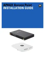
AP6522 Access Point

2.

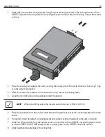
Mark two points (for drill holes) 4.08 inches (103.7 mm) apart on a horizontal line.

3.

At each point, drill a hole in the wall, insert an anchor, screw into the anchor the wall mounting screw and
stop when there is 1mm between the screw head and the wall.

4.

If required, install and attach a Kensington security cable (customer supplied) to the unit’s lock port.

5.

Attach an Ethernet cable from the access point to a controller with an 802.3af-compatible power source
or use the PWRS-14000-148R power supply to supply power to the AP6522 (once fully cabled).

6.

Place the middle of each of the case’s mount slots over the screw heads.

7.

Slide the case down along the mounting surface to hang the mount slots on the screw heads.

8.

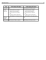
Verify the unit has power by observing that the LEDs are lit or flashing.

NOTE

When pre-drilling a hole the recommended hole size is 2.8mm (0.11in.).

CAUTION

If not using a 802.3af capable controller to power the AP6522, ensure
only the AP6522’s designated power supply (PWRS-14000-148R) is
used to supply power to the access point. Using an incorrectly rated
power supply could damage the unit and void the product warranty.
Do not actually connect to the power source until the cabling portion
of the installation is complete.

!

Summary of Contents for AP6522

Page 1: ...AP6522 Access Point INSTALLATION GUIDE ...

Page 2: ...2 AP6522 Access Point MOTOROLA SOLUTIONS and the Stylized M Logo are registered in the US Patent Trademark Office Motorola Solutions Inc 2012 All rights reserved ...

Page 3: ...ount 15 2 8 External Antenna Suspended Ceiling Tile Plenum Mount 17 2 9 AP6522 External Antenna Model Antenna Options 18 2 10 LED Indicators 20 3 0 Initial Access Point Configuration 22 4 0 Specifications 38 4 1 AP6522 Integrated Antenna Model Electrical Characteristics 38 4 2 AP6522 Integrated Antenna Model Physical Characteristics 38 4 3 AP6522 External Antenna Model Electrical Characteristics 3...

Page 4: ...e of adopting and managing up to 24 additional AP6522 access points a Standalone access point or a Dependent mode access point managed by its connected controller If new to Motorola Solutions access point technology refer to the WiNG Access Point System Reference Guide to familiarize yourself with access point technology and the feature set supported by the WiNG operating system The guide is avail...

Page 5: ...gn installation responsibility to the appropriate personnel Identify and document where all installed components are located Ensure adequate dust free ventilation to all installed equipment Identify and prepare Ethernet and console port connections Verify cable lengths are within the maximum allowable distances for optimal signal transmission 1 4 Package Contents An AP6522 access point is availabl...

Page 6: ...ompliant power from an external source The illustration below is of an integrated antenna model The AP6522 access point comes with dual radios supporting 802 11abgn The access point contains runtime firmware which enables the unit to boot after a power up The runtime firmware on the access point and the firmware downloaded from the connected controller can be updated via the Ethernet interface NOT...

Page 7: ... 5 or better Ethernet cable to a compatible 802 3af power source and run the cable to the installation site Ensure there is sufficient slack on the cable to perform the installation steps Part Number Description AP 6522 66030 US Dual 802 11n radio AP6522 Plastic enclosure with internal antennas For use in the US deployments only AP 6522 66030 EU Dual 802 11n radio AP6522 Plastic enclosure with int...

Page 8: ...an area like even placement of a light bulb provides even efficient coverage Place the access point using the following guidelines Install the access point at an ideal height of 10 feet from the ground Orient the access point antennas vertically for best reception applies to external antenna models only To maximize the access point s radio coverage area Motorola Solutions recommends conducting a s...

Page 9: ...n Guide 9 2 4 2 Wall Mount Procedure 1 Orient the case on the wall by its width or length CAUTION To ensure proper operation of an AP6522 access point ensure it is mounted in the correct orientation as shown above ...

Page 10: ...ply power to the AP6522 once fully cabled 6 Place the middle of each of the case s mount slots over the screw heads 7 Slide the case down along the mounting surface to hang the mount slots on the screw heads 8 Verify the unit has power by observing that the LEDs are lit or flashing NOTE When pre drilling a hole the recommended hole size is 2 8mm 0 11in CAUTION If not using a 802 3af capable contro...

Page 11: ... cabled 3 Align the bottom of the T bar with the back of the case 4 Orient the case by its length and the length of the T bar 5 Rotate the case 45 degrees clockwise or about 10 o clock 6 Push the back of the case onto the bottom of the T bar 7 Rotate the case 45 degrees counter clockwise The clips click as they fasten to the T bar 8 Verify the unit has power by observing the LEDs CAUTION If not us...

Page 12: ...chors 2 6 1 Wall Mount Hardware Two customer provided wide shoulder Phillips pan head self tapping screws M3 5 x 0 6 x 20 mm Two wall anchors customer supplied Security cable optional 2 6 2 Wall Mount Procedure New Installation This section describes a new AP6522 installation with no previous access point existing on the intended wall surface NOTE The following screws are recommended ANSI Standard...

Page 13: ...les 4 At each point drill a hole in the wall and insert the anchor 5 Place the access point on the anchor Insert screws through the access point s mounting ears and into the anchor 6 If required install and attach a Kensington security cable customer supplied to the unit s lock port 7 Attach an Ethernet cable from the access point to a controller with an 802 3af compatible power source or use the ...

Page 14: ...mply remove the existing legacy model access point from its mounting screws leave the mounting hardware in place and install the new external antenna model AP6522 directly on to the existing mounting hardware The cabling procedure for such a replacement is as described in the previous section CAUTION If not using a 802 3af capable controller to power the AP6522 ensure only the AP6522 s designated ...

Page 15: ... tile raised slip the T Bar bracket on to the exposed T Bar flange 5 Lower the ceiling tile and verify the stability of the T Bar mounting bracket connection There will be no stability in this assembly until the ceiling tile is lowered on to the T Bar to secure the mounting hardware 6 Verify the unit has power by observing the LEDs 2 7 2 Suspended Ceiling T Bar Mount Procedure Using Ceiling Mount ...

Page 16: ...tible power source 8 Verify the unit has power by observing the LEDs CAUTION If not using an 802 3af capable controller to power the AP6522 ensure only the AP6522 s designated power supply PWRS 14000 148R is used to supply power to the access point Using an incorrectly rated power supply could damage the unit and void the product warranty Do not actually connect to the power source until the cabli...

Page 17: ...supply to supply power to the AP6522 once fully cabled 7 Verify the access point is receiving power by observing the LEDs 8 Place the ceiling tile back in its frame NOTE Notes or warnings about suspended ceiling mounts apply to all installations where the unit is placed on suspended ceiling tile CAUTION Motorola Solutions does not recommend mounting the AP6522 access point directly to any suspende...

Page 18: ...otorola Solutions supports two antenna suites for AP6522 External Antenna models One antenna suite supporting the 2 4 GHz band and another antenna suite supporting the 5 GHz band Select an antenna model best suited to the intended operational environment of your access point ...

Page 19: ...tion refer to http supportcentral motorola com support product manuals do Part Number Antenna Type ML 2452 APA2 01 Dipole Antenna ML 2499 SD3 01R Patch Antenna ML 2499 HPA3 01R Omni Antenna ML 2452 PNA5 01R Panel Antenna ML 2452 PTA3M3 036 Omni Antenna ML 2452 APAG2A1 01 Black ML 2452 APAG2A1 02 White Dipole Antenna Part Number Antenna Type ML 2452 APA2 01 Dipole Antenna ML 5299 PTA1 01R Patch Ant...

Page 20: ...indicators on the front of the case With the External Antenna models mounted above a ceiling LEDs are at the center of an oval badge on the ceiling The LEDs provide a status display indicating error conditions transmission and network activity for the 5 GHz 802 11an amber radio or the 2 4 GHz 802 11bgn green radio ...

Page 21: ...second interval If this radio band is disabled Off If there is activity on this band Blink interval at 1 time per second If this radio band is enabled Blink at 5 second interval If this radio band is disabled Off If there is activity on this band Blink interval at 1 time per second Firmware Update On Off Sensor Mode Blink interval at 5 times a second Blink interval at 5 times a second ...

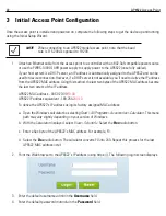
Page 22: ...s of the IP address AP6522 MAC address 00 C0 23 00 F0 0A AP6522 IP address equivalent 169 254 240 10 To derive the AP6522 s IP address using its factory assigned MAC address a Open the Windows calculator be selecting Start All Programs Accessories Calculator This menu path may vary slightly depending on your version of Windows b With the Calculator displayed select View Scientific Select the Hex r...

Page 23: ...2 s initial configuration 7 If this is the first time the management interface has been accessed a dialogue displays to start the wizard Select Start Wizard to run the wizard NOTE When logging in for the first time you re prompted to change the password to enhance device security in subsequent logins NOTE If you get disconnected when running the wizard you can connect again with the access point s...

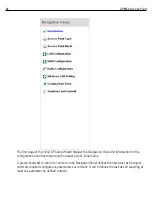
Page 24: ... the configuration activities comprising the access point s initial setup A green checkmark to the left of an item in the Navigation Panel defines the listed task as having its minimum required configuration parameters set correctly A red X defines the task as still requiring at least one parameter be defined correctly ...

Page 25: ... Panel Select Back to revert to the previous screen in the Navigation Panel without saving your updates 9 Select Next The Initial AP Setup Wizard displays the Access Point Type screen to define the access point s Standalone versus Virtual Controller AP functionality and the way the access point is adopted to a controller NOTE While you can navigate to any page in the navigation panel you cannot co...

Page 26: ...AP Setup Wizard An adopted access point obtains its configuration from a profile stored on its managing controller Any manual configuration changes are overwritten by the controller upon reboot Select the Automatic controller discovery option to enable the access point to be discovered and adopted using layer 2 settings If preferring layer 3 adoption select the Static Controller Configuration opti...

Page 27: ...whether the access point receives an IP address using DHCP or if IP resources are provided statically 11 Select Next The Initial AP Setup Wizard displays the Access Point Mode screen to define the access point s routing or bridging mode functionality ...

Page 28: ...gle access point Bridge Mode In Bridge Mode the AP depends on an external router for routing LAN and WAN traffic Routing is generally used on one device whereas bridging is typically used in a larger network Thus select Bridge Mode when deploying this access point with numerous peer APs supporting clients on both the 2 4 and 5GHz radio bands 13 Select Next The Initial AP Setup Wizard displays the ...

Page 29: ...Name Server DNS resources as those fields will become enabled on the bottom portion of the screen Use on board DHCP server to assign IP addresses to wireless clients Select the checkbox to enable the access point s DHCP server to provide IP and DNS information to clients on the LAN interface Range Enter a starting and ending IP Address range for client assignments on the LAN interface Avoid assign...

Page 30: ... Server providing DNS services for the access point s LAN interface 15 Select Next The Initial AP Setup Wizard displays the WAN Configuration screen to set the access point s WAN interface configuration 16 Set the following DHCP and Static IP Address Subnet information for the WAN interface Use DHCP Select the checkbox to enable an automatic network address configuration using the access point s D...

Page 31: ... radio for WLAN client support in either the selected 2 4 or 5GHz radio band Radio Frequency Band Select either the 2 4GHz or 5 0GHz radio band to use with the radio when selected as a Data Radio The selected band is used for WLAN client support Considers selecting one radio for 2 4GHz and another for 5GHz support when supporting clients in both the 802 11bg and 802 11n bands Power Level Use the s...

Page 32: ...and scan for noise and interference only when initialized Configure as a Sensor Radio Select this option to dedicate the radio to sensor support exclusively When functioning as a sensor the radio scans in sensor mode across all channels within the 2 4 and 5 0GHz bands to identify potential threats within the access point managed network If dedicating a radio as a sensor resource a primary and seco...

Page 33: ...ge and verification of certificates If using this option define whether a local or external RADIUS authentication resource is used WPA Key If a WPA key is required PSK Authentication and WPA2 Encryption enter an alphanumeric string of 8 to 63 ASCII characters or 64 HEX characters as the primary string both transmitting and receiving authenticators must share The alphanumeric string allows characte...

Page 34: ...sername up to X characters in length The username cannot be revised if modifying the user configuration This is a required parameter Password Provide or modify a password between X X characters in length entered each time a requesting client attempts access to the AP managed network using the access point s onboard RADIUS server This is a required parameter Confirm Password Re enter or modify the ...

Page 35: ...on Location Define the location of the access point The Location parameter acts as a reminder of where the AP is deployed within the Motorola Solutions managed wireless network Contact Specify the contact information for the administrator The credentials provided should accurately reflect the individual responding to service queries Country Select the Country where the access point is deployed The...

Page 36: ... Time calendar date time and AM PM designation 30 Optionally enter the IP address of a server used to provide system time to the access point Once the IP address is entered the Network Time Protocol NTP functionality is engaged automatically for synchronization with the NTP resource 31 Select Next The Initial AP Setup Wizard displays the Summary and Commit screen to summarize the screens pages and...

Page 37: ...tion If additional changes are warranted based on the summary either select the target page from the Navigational Panel or use the Back and Next buttons to scroll to the target screen For information on how use a Motorola Solutions RFS Series controller to manage an AP6522 access point refer to http supportcentral motorola com support product manuals do ...

Page 38: ...ing Current Voltage 12VDC 1A accessory power connector 48V 0 25A PoE connector Dimensions 9 38 inches x 7 5 inches x 1 38 inches 23 82 cm x 19 50 cm x 3 50 cm Housing Plastic Weight 0 90 lbs 0 40 kg Operating Temperature 32 F to 104 F 0 C to 40 C Storage Temperature 40 F to 185 F 40 C to 85 C Operating Humidity 5 to 95 Relative Humidity non condensing Storage Humidity 85 Relative Humidity non cond...

Page 39: ...ent Voltage 12VDC 1A accessory power connector 48V 0 25A PoE connector Dimensions 7 88 inches x 5 00 inches x 1 00 inches 20 01 cm x 12 70 cm x 2 54 cm Housing Metal Weight 1 45 lbs 0 65 kg Operating Temperature 32 F to 104 F 0 C to 40 C Storage Temperature 40 F to 185 F 40 C to 85 C Operating Humidity 5 to 95 Relative Humidity non condensing Storage Humidity 85 Relative Humidity non condensing Op...

Page 40: ...36 48 and 54Mbps 802 11a 6 9 12 18 24 36 48 and 54Mbps 802 11n MCS 0 15 up to 300Mbps Wireless Medium Direct Sequence Spread Spectrum DSSS Orthogonal Frequency Division Multiplexing OFDM Spatial multiplexing MIMO Network Standards 802 11a 802 11b 802 11g 802 3 802 11n Draft 2 0 Maximum Available Transmit Power Maximum available conducted transmit power per chain 2 4 GHz 21dBm Maximum available con...

Page 41: ...to the device signifying the radio s is are approved for use in the following countries United States Canada Japan China S Korea Australia and Europe Please refer to the Declaration of Conformity DoC for details of other country markings This is available at http www motorola com doc Note For 2 4GHz or 5GHz Products Europe includes Austria Belgium Bulgaria Czech Republic Cyprus Denmark Estonia Fin...

Page 42: ... radio devices in fuel depots chemical plants etc and areas where the air contains chemicals or particles such as grain dust or metal powders Safety in Hospitals Wireless devices transmit radio frequency energy and may affect medical electrical equipment When installed adjacent to other equipment it is advised to verify that the adjacent equipment is not adversely affected Pacemakers Pacemaker man...

Page 43: ... desktop of similar configurations must operate with a minimum separation distance of 20 cm from all persons Power Supply UseONLYa LISTEDMotorola Typeno PWRS 14000 148R 12VDC 4 16A direct plug inpowersupply marked Class 2 IEC60950 1 SELV This device can be powered from a 802 3af compliant power source which is certified by the appropriate agencies Use of alternative Power Supply will invalidate an...

Page 44: ...ice complies with Part 15 of the FCC Rules Operation is subject to the following two conditions 1 this device may not cause harmful interference and 2 this device must accept any interference received including interference that may cause undesired operation Radio Frequency Interference Requirements Canada This Class B digital apparatus complies with Canadian ICES 003 Cet appareil numérique de la ...

Page 45: ... from http www motorola com doc Korea Warning Statement for Class B Other Countries Australia Use of 5GHz RLAN s in Australia is restricted in the following band 5 50 5 65GHz Brazil Declarações Regulamentares para AP6522 Brasil Nota A marca de certificação se aplica ao Transceptor modelo AP6522 Este equipamento opera em caráter secundário isto é não tem direito a proteção contra interferência prej...

Page 46: ...46 AP6522 Access Point Taiwan 5 25 5 35 䌿丏ᐊܻ П 䊛㿞 ڇ 䔌䀁 ˈ 䰤ᮐᅸܻՓ Korea Turkish WEEE Statement of Compliance EEE Yönetmeliğine Uygundur ...

Page 47: ...a al fine di consentirne il riciclaggio Per informazioni sulle modalità di restituzione visitare il seguente sito Web http www motorola com recycling weee Português Para clientes da UE todos os produtos no fim de vida devem ser devolvidos à Motorola para reciclagem Para obter informações sobre como devolver o produto visite http www motorola com recycling weee Nederlands Voor klanten in de EU alle...

Page 48: ... http www motorola com recycling weee Românesc Pentru clienţii din UE Toate produsele la sfârşitul duratei lor de funcţionare trebuie returnate la Motorola pentru reciclare Pentru informaţii despre returnarea produsului accesaţi http www motorola com recycling weee Slovenski Za kupce v EU vsi izdelki se morajo po poteku življenjske dobe vrniti podjetju Motorola za reciklažo Za informacije o vračil...

Page 49: ...Central Web site located at http supportcentral motorola com provides information and online assistance including developer tools software downloads product manuals and online repair requests Manuals http supportcentral motorola com support product manuals do Part Number Description AP 6522 66030 US Dual 802 11n radio AP6522 Plastic enclosure with internal antennas For use in the US deployments on...

Page 50: ...opyright laws of the United States and international copyright treaties The Software is licensed not sold This Agreement does not give Licensee any rights not expressly granted herein 3 INTELLECTUAL PROPERTY CONTENT All title and intellectual property rights in and to the Software including but not limited to any images photographs animations video audio music text and applets incorporated into th...

Page 51: ... greater of the amount actually paid by Licensee for the Software or U S 5 00 The foregoing limitations exclusions and disclaimers shall apply to the maximum extent permitted by applicable law even if any remedy fails its essential purpose 9 INDEMNITY Licensee agrees that Licensor shall have no liability whatsoever for any use Licensee makes of the Software Licensee shall indemnify and hold harmle...

Page 52: ... the laws of the State of New York without regard to the conflicts of law provisions thereof The application the United Nations Convention of Contracts for the International Sale of Goods is expressly excluded Unless waived by Licensor for a particular instance any action or proceeding arising out of this Agreement must be brought exclusively in the state or federal courts of New York and Licensee...

Page 53: ...中可能会也可能不会含有所有所列的部件 This table was created to comply with China RoHS requirements for Motorola Solutions AP6522 Access Point 部件名称 Parts 有毒有害物质或元素 铅 Pb 汞 Hg 镉 Cd 六价铬 Cr6 多溴联 苯 PBB 多溴二苯 醚 PBDE 金属部件 Metal Parts O O O O O O 电路模块 Circuit Modules X O O O O O 电缆及电缆组件 Cables and Cable Assemblies X O O O O O 塑料和聚合物部件 Plastic and Polymeric Parts O O O O O O 光学和光学组件 Optics and Optical Components O O O O O O 电...

Page 54: ...54 AP6522 Access Point ...

Page 55: ...Installation Guide 55 ...

Page 56: ...MOTOROLA MOTO MOTOROLA SOLUTIONS and the Stylized M Logo are trademarks or registered trademarks of Motorola Trademark Holdings LLC and are used under license All other trademarks are the property of their respective owners 2012 Motorola Solutions Inc All Rights Reserved 72 162462 01 Revision B August 2012 ...

Reviews: