background image

Installation Guide

41

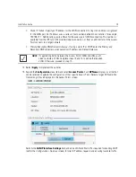
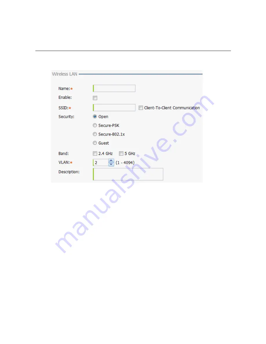
16. To create a new WLAN, select 

+ Add

 from the upper, left-hand side of the 

Wireless LAN

 field.

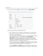
17. Set the following configuration attributes for the new WLAN:

Name 

- Provide a unique name for the WLAN as its network identifier. This is a required setting.

Enable - 

Select this setting to enable this WLAN within the Access Point managed network and 

provide some measure of data protection. 

SSID

 - Specify the WLAN's SSID. The WLAN SSID is case sensitive and alphanumeric. SSID length 

should not exceed 32 characters. This is a required setting. Select 

Client-To-Client 

Communication

 to enable client interoperability within this WLAN. The default is disabled, 

meaning clients are 

not

 allowed to exchange packets with other clients. It does not necessarily 

prevent clients on other WLANs from sending packets to this WLAN, but if this setting is disabled 
on the other WLAN, clients are not permitted to interoperate at all.

WLAN Type -

 The screen displays with the 

Open

 option selected. Naming and saving such a policy 

(as is) would provide no security and might only make sense in a network wherein no sensitive data 
is either transmitted or received. This default setting is 

not

 recommended. 

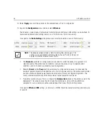
If selecting 

Secure-PSK

, enter a 

WPA2 Key

 to password protect the WLAN. Define whether the 

key is entered in ASCII or HEX characters. Selecting 

Show

 to expose the key is not recommended.

Summary of Contents for AP-7562

Page 1: ...AP 7562 ACCESS POINT INSTALLATION GUIDE ...

Page 2: ... AccessPoint Zebra and the Zebra head graphic are registered trademarks of ZIH Corp The Symbol logo is a registered trademark of Symbol Technologies Inc a Zebra Technologies company 2015 Symbol Technologies Inc ...

Page 3: ...U 8 1 3 7 AP 7562 Single Band 5 GHz Antenna EU 8 1 4 Hardware and Mounting Accessories 9 1 5 AP 7562 Mounting Accessories 9 1 6 AP 7562 Weatherized Ethernet Accessory 9 1 7 Package Contents 10 1 8 Hardware Installation Guidelines 10 1 8 1 Precautions 11 1 8 2 Warnings 12 1 9 Access Point Placement 13 1 10 AP 7562 Hardware Overview 13 1 10 1 AP 7562 Ports and Connections 13 1 10 2 AP 7562 Antenna C...

Page 4: ...Statement 47 5 4 Health and Safety Recommendations 47 5 4 1 Warnings for the Use of Wireless Devices 47 5 4 2 Potentially Hazardous Atmospheres 47 5 5 RF Exposure Guidelines 48 5 6 Power Supply 49 5 7 Radio Frequency Interference Requirements FCC 49 5 7 1 Radio Transmitters Part 15 50 5 8 Radio Frequency Interference Requirements Canada 50 5 9 CE Marking and European Economic Area EEA 51 5 10 Stat...

Page 5: ...Installation Guide 5 ...

Page 6: ... including wired networks Once adopted by a WLAN or Integrated Services Controller running WiNG firmware the AP 7562 is managed as an Adaptive AP running the WiNG network management protocol WiNG networks extend the current differentiation that Adaptive APs offered to the next level by now having the services and security available at every point in the network The traffic flow is optimized to pre...

Page 7: ...Access Point outdoor IP67 dual radio 3x3 3 802 11 a b g n ac radio SKU US AP 7562 67040 EU AP 7562 Access Point outdoor IP67 dual radio 3x3 3 802 11 a b g n ac radio SKU EU AP 7562 67040 WR AP 7562 Access Point outdoor IP67 dual radio 3x3 3 802 11 a b g n ac radio SKU WR NOTE All AP 7562 Access Points ship with one weatherized Ethernet adapter AP 7562 Access Points do not ship with the Mounting Ki...

Page 8: ...nna Type 2 4 GHz Peak Gain 5 2 GHz Peak Gain ML 2452 HPAG4A6 01 Dipole 4 0 7 3 ML 2452 HPA6X6 036 Dipole 4 0 7 3 ML 2452 HPA6 01 Dipole 5 3 6 1 ML 2452 PNA5 01R Panel 5 5 6 0 ML 2452 PNL3M3 1 Polarized Panel 9 7 9 2 Part Number Antenna Type 2 4 GHz Peak Gain ML 2499 FHPA5 01R Dipole 5 3 ML 2499 HPA4 01 Dipole 4 5 ML 2499 5PNL 72 N Panel 6 5 Part Number Antenna Type 5 2 GHz Peak Gain ML 5299 HPA5 0...

Page 9: ...EU 1 3 6 AP 7562 Single Band 2 4 GHz Antennas EU 1 3 7 AP 7562 Single Band 5 GHz Antenna EU Index Antenna Type Part Number Elevation Gain 1 Dipole ML 5299 HPA5 01 2 53 2 Dipole ML 2452 HPAG4A6 01 5 7 3 Dipole ML 2452 HPA6X6 036 3 9 4 Dipole ML 2452 HPA6 01 4 09 Part Number Antenna Type 2 4 GHz Peak Gain 5 2 GHz Peak Gain ML 2452 HPAG5A8 01 Dipole 7 5 8 0 ML 2452 PNA7 01R Panel 8 0 12 0 ML 2452 PNL...

Page 10: ...part number listed in the following table Refer to the installation instructions included with the RJ45 weatherized connector plug for proper procedure to form a drip loop with the cable Part Number Description AP PSBIAS 7161 US Outdoor IP66 802 3AT gigabit Ethernet power injector 100 240 VAC US AP PSBIAS 7161 WW Outdoor IP66 802 3AT gigabit Ethernet power injector 100 240 VAC International KT 153...

Page 11: ...ately Each AP 7562 Access Point see AP 7562 Hardware on page 7 includes the following parts AP 7562 Access Point Weatherproof RJ45 plug kit AP 7562 Access Point Installation Guide this document 1 8 Hardware Installation Guidelines NOTE Record the serial numbers on the shipping cartons and AP 7562 Access Points for warranty claims and reference during software download procedures CAUTION All device...

Page 12: ...erly attach the grounding cable to the Access Point refer to AP 7562 Grounding Post on page 17 For Ethernet and lightning protection it is recommended that a commercially available off the shelf Lightning Protection Unit LPU be used on all shielded CAT5E Ethernet connections The LPU should be rated for outdoor use For the best possible protection each Access Point requires an LPU be installed adja...

Page 13: ...nditions that could cause a power surge Verify there is adequate ventilation around the device and that ambient temperatures meet equipment operation specifications Avoid contact with overhead power lines Take precautions to avoid injury from falling tools and equipment Crews should wear hard hats in and around the installation work site Be aware of vehicular traffic in and around the installation...

Page 14: ...ion when deploying devices 1 10 AP 7562 Hardware Overview The AP 7562 is a 3x3 3 802 11ac Access Point utilizing one 2 4 GHz 802 11n radio and one 5 GHz 802 11ac radio An AP 7562 must be installed by trained professionals familiar with RF planning and regulatory limits defined by the regulatory bodies of the country where the devices are being deployed All common precautions for grounding and Elec...

Page 15: ...562 67040 EU and AP 7562 67040 WR are configured with six N type connectors to support two active WLAN data radios WARNING Antenna ports where no antenna is mounted must be properly terminated using an approved IP67 terminator WARNING All antenna connectors should be covered with weatherproofing tape ...

Page 16: ...ccessPoint 1 10 3 Antenna Mounting Guidelines The following are examples of acceptable mounting for dipole antenna deployments The following are examples of acceptable mounting methods for panel antenna deployments ...

Page 17: ...to securely attach the grounding cable to the grounding post Use an 8mm socket and driver to tighten the grounding screw to 30 inch pounds lbf in Attach a ring lug to the grounding cable and use a grounding screw to securely attach the ring lug to the Access Point Use an 8mm socket and driver to tighten the grounding screw to 30 inch pounds lbf in WARNING The grounding cable for an AP 7562 must be...

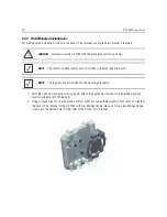
Page 18: ...pability The VMM operates on Power over Ethernet PoE and is rugged enough for installation in commercial and public safety vehicles for mobile deployments Zebra recommends using the vehicle mount kit KT 158767 01 for mobile deployments To install the Access Point VMM 1 Remove rubber plugs from four screw holes on the LED side of the AP 7562 Position unit with screw holes facing upwards 2 Put the f...

Page 19: ... 19 4 Put the stiffener plate on the chassis mount with the key hole and four screw holes aligned 5 Insert four screws with washers through the holes of the three plates and into the screw holes on the bottom of the VMM ...

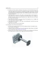
Page 20: ...ws or bolts not provided 10 Securely attach the AP 7562 top bracket sub assembly to the vehicle mount with the four pre installed thumb screws Tighten the screws to 90 inch pounds lbf in using a philips screwdriver or pliers 11 Attach three RP SMAF adapters part number 25 90263 02R to the N connectors on the active mobile radio on the VMM Radio 1 ports are labeled R1 A R1 B and R1 C Radio 2 ports ...

Page 21: ...ce design operated outside of the allowed specifications for power of an AP 7161 running as an AP 7161 VMM The following table shows a number of potential power sources and corresponding industry options to power an AP 7562 VMM WARNING Exceeding these listed power requirements can invalidate warranty Potential Vehicular Mobile Power Sources Required Source 12V battery DC DC convertor or DC PoE inj...

Page 22: ...cond interval If this radio band is disabled Off If there is activity on this band Blink interval at 1 time per second If this radio band is enabled Blink at 5 second interval If this radio band is disabled Off If there is activity on this band Blink interval at 1 time per second Firmware Update Off On Locate AP Mode LEDs blink in an alternating green red and amber pattern using an irregular blink...

Page 23: ...oint bracket left angle adapter bracket center and pole mount bracket right sections The Access Point bracket and angle adapter bracket can be rotated plus or minus 15 degrees and tilted up to 45 degrees to orient the unit for optimal positioning The following ancillary hardware to assemble the mounting bracket is included in the kit A torque wrench or ratchet with a 10mm adapter or an adjustable ...

Page 24: ...s more than 3 inches in diameter use the extension arm kit KT 150173 01 to provide a minimum standoff distance of twelve inches to avoid interference with the antennas The extension arm kit can also be used in combination with the any of the brackets from the mounting bracket kit ...

Page 25: ...of the mounting hardware kit at the desired position on the pole using band clamps up to 3 4 inch width or a 1 2 inch x 4 inch wide U bolt and nuts For poles greater than 3 inches in diameter attach the pole mount bracket using band clamps Description Quantity 1 2 inch hex head nut 2 1 2 inch x 3 4 inch hex head bolt 2 CAUTION Always mount the AP 7562 with the black gore vent facing down NOTE The ...

Page 26: ...read two 1 2 inch nuts onto the U bolt 2 Position the U bolt on the pole and place the pole mount bracket on the U bolt Adjust the two 1 2 inch inner nuts until the pole mount bracket is against the pole and the U bolt can be secured tightly to the pole at the desired mounting location 3 Place the angle adapter bracket on the U bolt with the open slot connections on the bottom and align it with th...

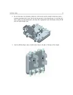
Page 27: ...oriented toward the bottom side of the AP with the gore vent Using a torque wrench or a ratchet and a 10mm socket or an adjustable wrench attach but don t tighten the Access Point bracket to the AP 7562 with the four M6 flange screw 5 Insert two M6 hex flange screws into the bottom holes on the sides of the Access Point bracket ...

Page 28: ... bottom holes on the sides of the Access Point bracket into the open slot connections on the bottom of the angle adapter bracket 7 Rotate the Access Point bracket upward and align the top holes on the sides with the top holes on the angle adapter bracket Insert two M6 hex flange screws into the top holes on the angle adapter bracket ...

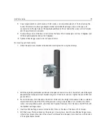
Page 29: ... the angle adapter bracket positioned so the open connector slots are on the bottom attach the angle adapter bracket to the pole mount bracket using two 1 2 inch bolts and nuts Tighten the nuts to 300 inch pounds lbf in 3 Position the Access Point bracket so the bottom of the with the straight not bevel cut sides is oriented toward the bottom side of the AP with the gore vent Using a torque wrench...

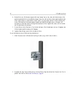
Page 30: ...nd the top holes on the angle adapter bracket Do not tighten the screws until all rotation and tilt adjustments are complete 7 To adjust the position of the Access Point rotate the Access Point bracket plus or minus 15 degrees and tilt the angle adapter bracket up to 45 degrees 8 Tighten all hex flange screws to 60 inch pounds lbf in To use the extension arm with the mounting hardware kit 1 Attach...

Page 31: ...our M6 hex flange screws The two oval holes must be positioned on the short sides of the Access Point Tighten the hex flange screws to 60 inch pounds lbf in the unit 4 With the Access Point positioned so the gore vent is facing down attach the extension arm to the Access Point bracket with two 1 2 inch bolts and nuts Tighten the nuts to 300 inch pounds lbf in ...

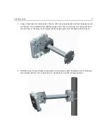
Page 32: ...bolts 2 Using a torque wrench or a ratchet and a 10mm socket or an adjustable wrench attach but don t tighten the Access Point bracket to the AP 7562 with four M6 hex flange screws and insert two M6 hex flange screws into the bottom holes on the sides of the Access Point bracket CAUTION Always mount the AP 7562 with the black gore vent facing down NOTE The U bolt and band clamps are not included i...

Page 33: ...screws until all rotation and tilt adjustments are complete 5 To adjust the position of the Access Point rotate the Access Point bracket plus or minus 15 degrees and tilt the angle adapter bracket up to 45 degrees 6 Use a torque wrench or a ratchet and a 10mm socket or an adjustable wrench to tighten all screws when all adjustments are complete 7 Tighten all hex flange screws to 60 inch pounds lbf...

Page 34: ...ped with a cable with open leads Mounting kits are not supplied see Hardware and Mounting Accessories on page 10 for mounting kit part numbers If located within 100 meters of the controller and a PoE port is available the AP 7562 Access Point can also be connected directly to a WLAN or Integrated Services Controller running WiNG 5 6 or higher A standard CAT5E cable can be used to provide the conne...

Page 35: ...ress 00 C0 23 00 F0 0A Zero config IP address 169 254 240 10 To derive the Access Point s IP address using its MAC address a Open the Windows calculator by selecting Start All Programs Accessories Calculator This menu path may vary slightly depending on your version of Windows b With the Calculator displayed select View Scientific Select the Hex radio button c Enter a hex byte of the Access Point ...

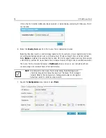
Page 36: ...to implement the selected Country Code SKU s only support certain countries for example a US SKU only includes US Guam Puerto Rico American Samoa US Virgin Islands and Mariana Island The Access Point automatically displays a Dashboard where users can assess network health and conduct a diagnostic review of Access Point performance 7 Expand the Configuration menu item and select Basic NOTE At some ...

Page 37: ...those Access Points managed by this Virtual Controller will list this Access Point s AP Name as its own Only one Virtual Controller can be designated Timezone Use the drop down menu to specify the geographic timezone where the Access Point is deployed Different geographic time zones have daylight savings clock adjustments so specifying the timezone correctly is important to account for geographic ...

Page 38: ...rver to a host Some of these parameters are IP address network mask and gateway The WAN and LAN ports should not both be configured as DHCP clients Static IP Select this option to bypass DHCP address allocation resources and manually set the IP address for the Access Point s WAN connection Manually provide the Access Point s Static IP Mask and Default Gateway PPPoE Settings Optionally enable Point...

Page 39: ...S server resource s numerical IP address and Default Gateway 12 Select Apply to implement the updates 13 Expand the Configuration menu item and select Access Points Each AP Name displays as a link that can be selected to update the configuration of that specific Access Point Select a target AP Name link from amongst those displayed in the Access Points screen Refer to the LAN IP Interface Settings...

Page 40: ...s the Power setting automatically configures radio power to not exceed the maximum power allowed by the defined country For static power settings the professional installer must ensure the configured power levels are compliant with local and regional regulations The county selected automatically limits the maximum output power that can be set For external antenna Access Points configure the Antenn...

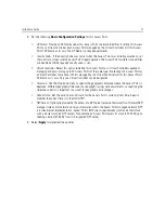
Page 41: ...tion to enable client interoperability within this WLAN The default is disabled meaning clients are not allowed to exchange packets with other clients It does not necessarily prevent clients on other WLANs from sending packets to this WLAN but if this setting is disabled on the other WLAN clients are not permitted to interoperate at all WLAN Type The screen displays with the Open option selected N...

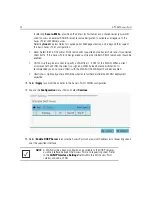
Page 42: ...a VLAN from 1 4 094 for this WLAN When a client associates with a WLAN the client is assigned a VLAN by load balance distribution Its recommended you do not use VLAN 1 with the WLAN if the WAN port has been enabled Description Optionally enter a WLAN description to further describe the WLAN s deployment objective 18 Select Apply to commit the updates to the Access Point s WLAN configuration 19 Exp...

Page 43: ...ilable to requesting clients 21 Select Apply to commit the updates to the Access Point s DHCP configuration 22 At this point you re ready to connect to the network using the security restrictions applied to the newly created WLAN Ensure the new secure WLAN has been enabled and check whether a client is able to access the network ...

Page 44: ...BaseT Ethernet 802 3at on GE1 LAN port Antenna Connectors 6 N Type console ports Console Port Outdoor rated RJ45 console port Multi Band Security Sensor Outdoor 24x7 Wireless Intrusion Prevention System WIPS Operating Temperature 22 F to 140 F 30 C to 60 C Storage Temperature 40 F to 185 F 40 C to 80 C Operating Humidity 5 to 95 RH non condensing IP Sealing IP 67 Operating Altitude 8 000 ft at 12 ...

Page 45: ...Installation Guide 45 4 3 Power Characteristics Operating Voltage 36 57 VDC Operating Current 375mA at 48V in 802 3at mode Integrated PoE 802 3af 802 3at ...

Page 46: ...tennas modifications or attachments could cause damage and may violate regulations 5 1 Wireless Country Approvals Regulatory markings are applied to the device signifying the radio s are approved for use in the following countries United States Canada Australia and Europe Please refer to the Declaration of Conformity DoC for details of other country markings This is available at www zebra com doc ...

Page 47: ...ilisateurs principaux c à d qu ils ont la priorité pour les bands 5250 5350 MHz et 5650 5850 MHz et que ces radars pourraient causer du brouillage et ou des dommages aux dispositifs LAN EL 5 4 Health and Safety Recommendations 5 4 1 Warnings for the Use of Wireless Devices Please observe all warning notices with regard to the usage of wireless devices 5 4 2 Potentially Hazardous Atmospheres Wirele...

Page 48: ...e Properly Only operate the device in accordance with the instructions supplied International The device complies with internationally recognized standards covering human exposure to electromagnetic fields from radio devices For information on International human exposure to electromagnet fields refer to the Declaration of Conformity DoC at www zebra com doc For further information on the safety o...

Page 49: ...will invalidate any approvals given to this unit and may be dangerous 5 7 Radio Frequency Interference Requirements FCC This equipment has been tested and found to comply with the limits for a Class B digital device pursuant to Part 15 of the FCC rules These limits are designed to provide reasonable protection against harmful interference in a residential installation This equipment generates uses...

Page 50: ...a type and its gain should be so chosen that the equivalent isotropically radiated power EIRP is not more than that permitted for successful communication The device could automatically discontinue transmission in case of absence of information to trans mit or operational failure Note that this is not intended to prohibit transmission of control or signaling information or the use of repetitive co...

Page 51: ...estricted in the following band 5 50 5 65 GHz Brazil UNWANTED EMISSIONS ALL PRODUCTS Regulatory Declarations for AP 7562 BRAZIL For more information consult the website http www anatel gov br Declarações Regulamentares para AP 7562 Brasil Nota A marca de certificação se aplica ao Transceptor modelo AP 7562 Este equipamento opera em caráter secundário isto é não tem direito a proteção contra interf...

Page 52: ...ón de este equipo está sujeta a las siguientes dos condiciones 1 es posible que este equipo o dispositivo no cause interferencia perjudicial y 2 este equipo o dispositivo debe aceptar cualquier interferencia incluyendo la que pueda causar su operación no deseada S Korea For a radio equipment using 2400 2483 5MHz or 5725 5825MHz the following two expression should be displayed ...

Page 53: ...Installation Guide 53 Taiwan 電磁波曝露量 MPE 標準值 1mW cm2 本產品使用時建議應距離人體 35 cm Ukraine Thailand ...

Page 54: ...t einde van hun levensduur naar Zebra te worden teruggezonden voor recycling Raadpleeg www zebra com weee voor meer informatie over het terugzenden van producten Polski Klienci z obszaru Unii Europejskiej Produkty wycofane z eksploatacji nale y zwróciæ do firmy Zebra w celu ich utylizacji Informacje na temat zwrotu produktów znajduj siê na stronie internetowej www zebra com weee Čeština Pro zákazn...

Page 55: ...ovenčina Pre zákazníkov z krajín EU Všetky výrobky musia byť po uplynutí doby ich životnosti vrátené spoločnosti Zebra na recykláciu Bližšie informácie o vrátení výrobkov nájdete na www zebra com weee Lietuvių ES vartotojams visi gaminiai pasibaigus jų eksploatacijos laikui turi būti grąžinti utilizuoti į kompaniją Zebra Daugiau informacijos kaip grąžinti gaminį rasite www zebra com weee Latviešu ...

Page 56: ... name Software type and version number Support responds to calls by e mail telephone or fax within the time limits set forth in support agreements If you purchased your product from a business partner contact that business partner for support Customer Support Web Sites The Support site located at www zebra com support provides information and online assistance including developer tools software do...

Page 57: ...License means the terms or conditions under which the Open Source Software is licensed Software i means proprietary software in object code format and adaptations translations decompilations disassemblies emulations or derivative works of such software ii means any modifications enhancements new versions and new releases of the software provided by Symbol Technologies and iii may contain items of ...

Page 58: ...s End User License Agreement Without limiting the general nature of these restrictions End User Customer will not make the Software available for use by third parties on a time sharing application service provider or service bureau basis or for any other similar commercial rental or sharing arrangement 3 2 End User Customer will not and will not allow or enable any third party to i reverse enginee...

Page 59: ...End User Customer will not transfer the Software or Documentation to any third party without Symbol Technologies prior written consent Symbol Technologies consent may be withheld at its discretion and may be conditioned upon transferee paying all applicable license fees and agreeing to be bound by this End User License Agreement 5 OWNERSHIP AND TITLE 5 1 Symbol Technologies its licensors and its s...

Page 60: ...nologies warrants that the Software when installed and or used properly will be free from reproducible defects that materially vary from its published specifications Symbol Technologies does not warrant that End User Customer s use of the Software or the Products will be uninterrupted or error free or that the Software or the Products will meet End User Customer s particular requirements 8 2 SYMBO...

Page 61: ...he right to repossess all copies of the Software in End User Customer s possession Within thirty 30 days after termination of End User Customer s right to use the Software End User Customer must certify in writing to Symbol Technologies that all copies of such Software have been returned to Symbol Technologies or destroyed 10 UNITED STATES GOVERNMENT LICENSING PROVISIONS 10 1 This Section applies ...

Page 62: ...al breach of this Agreement 11 3 Third Party Beneficiaries This End User License Agreement is entered into solely for the benefit of Symbol Technologies and End User Customer No third party has the right to make any claim or assert any right under this Agreement and no third party is deemed a beneficiary of this End User License Agreement Notwithstanding the foregoing any licensor or supplier of t...

Page 63: ...his End User License Agreement or any of the parties rights or obligations under this End User License Agreement The governing law will be that in effect prior to the applicability of UCITA 11 8 Dispute Resolution Unless End User Customer is a sovereign governmental entity any dispute arising from or in connection with this End User License Agreement shall be submitted to the sole and exclusive fo...

Page 64: ...eries ROHS Compliance 本表格依据 SJ T 11364 的规定编制 O 表示该有害物质在该部件所有均质材料中的含量均在 GB T 26572 规定的限量 要求以下 X 表示该有害物质至少在该部件的某一均质材料中的含量超出GB T 26572 规定 的限量要求 企业可在此处 根 据实际情况对上表中打 的技术原因进 行进一步说明 This table was created to comply with China RoHS requirements ...

Page 65: ...Installation Guide 65 ...

Page 66: ...66 AP 7562 AccessPoint ...

Page 67: ...Installation Guide 67 ...

Page 68: ...IL 60069 USA Zebra and the Zebra head graphic are registered trademarks of ZIH Corp The Symbol logo is a registered trademark of Symbol Technologies Inc a Zebra Technologies company 2015 Symbol Technologies Inc MN002313A01 Revision A October 2015 ...

Reviews: